Flowserve MJ Slurry User Manual
Page 17
MJ SLURRY USER INSTRUCTIONS ENGLISH 71569294 - 02/08
Page 17 of 42
®
that the pump and driver shafts are in parallel and
angular alignment under the normal operating
conditions of load and temperature
.
When the pump coupling and driver are assembled
at the factory, the units are aligned prior to shipment.
For pumps and drivers that operate at different
temperatures compensation must be made at the
initial alignment stage (when the units are at the
same temperature) to allow for thermal expansion
during operation. Consult the instruction manual
supplied with the driver for the manufacturer's
recommendations.
Shaft alignment is greatly simplified by the use of a
dial indicator with extension rods and a magnetic
base. Before taking readings, ensure that the pump
and driver mounting bolts are secure, and that the
thrust bearing housing is properly aligned in the
bearing frame or cartridge.
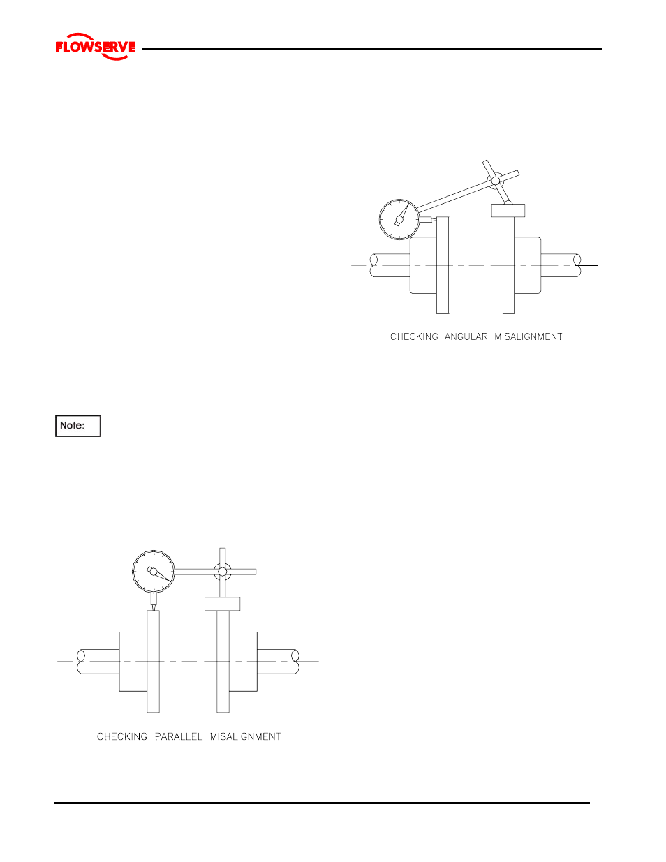
Parallel Alignment:
Mount the magnetic base on the pump half coupling
hub, either the face or O.D. as shown in the sketch.
Place the dial indicator button on the outside diameter
of the driver half coupling hub.
The length of extension rods should be kept at
a minimum to reduce deflection.
Rotate the pump shaft and record the dial reading at the
top, bottom and each side. Correct the parallel
alignment by adding or removing shims under the driver
and/or moving the driver horizontally. Repeat this
procedure until the maximum total indicator reading
(T.I.R.) is within 0.076 mm (0.003 inch.)
Angular Alignment:
Mount the magnetic base on the pump half coupling
hub, either the face or O.D. as shown in the sketch.
Move the dial indicator button to indicate on the face of
the driver half coupling hub as close to the outside
diameter as possible. When convenient the indicator
can be placed on the inside face to keep spans short.
Turn both shafts 360
° and record the dial readings at
90
° intervals. Adjust the shims under the motor as
required and repeat the procedure until the angular
alignment is within 0.0005 mm (T.I.R.) per mm (0.0005
inch per inch) of maximum hub diameter.
Repeat the checks on parallel and angular alignment,
ensuring the mounting bolts are secure, until the unit is
properly aligned. Note that correction in one direction
may affect the alignment in another direction. Re-check
the gap between the coupling hubs.
If any difficulty is encountered in achieving the
recommended alignment tolerances, the runout of the
pump and driver shafts and each coupling hub diameter
and face should be checked. Occasionally, due to
practical and unavoidable manufacturing tolerance
build-up associate with the pump, coupling and driver, it
may be necessary to match up the two coupling hubs in
the most advantageous relative angular position in order
to achieve an acceptable alignment.
Do not connect the couplings alignment is re-checked.
Complete piping as below and see sections 4.7, Final
shaft alignment check
up to and including section 5,
Commissioning, startup, operation and shutdown
before connecting driver and checking actual
rotation.