Flowserve MJ Slurry User Manual
Page 18
MJ SLURRY USER INSTRUCTIONS ENGLISH 71569294 - 02/08
Page 18 of 42
®
4.5.2.2 V-belt Drive Units:
Check that both sheaves are free of grease, rust, nicks
or burrs. Install the correct size sheave on the pump
shaft and locate the sheave axially to minimize
overhang. Re-check the impeller axial clearance and
ensure that the pump is properly secured to the
baseplate. Install the driver on the adjustable base
provided and install the driver sheave in line with the
pump sheave. Ensure that the sheaves are tight on the
shafts. With a dial indicator, check the runout on the
periphery and face of each sheave to ensure that each
is running true. Tighten the adjustable base and check
that the driver rotation in the correct direction and that
vibration levels are not unacceptable.
Before starting the driver, refer to the
manufacturer’s instruction manual. The correct rotation
of the pump shaft is marked on the pump casing or
frame.
Check that all belts making up one drive set have
matched code numbers. Loosen the adjustable base
and install the belts in their proper grooves. Adjust the
center distance between the sheaves to obtain proper
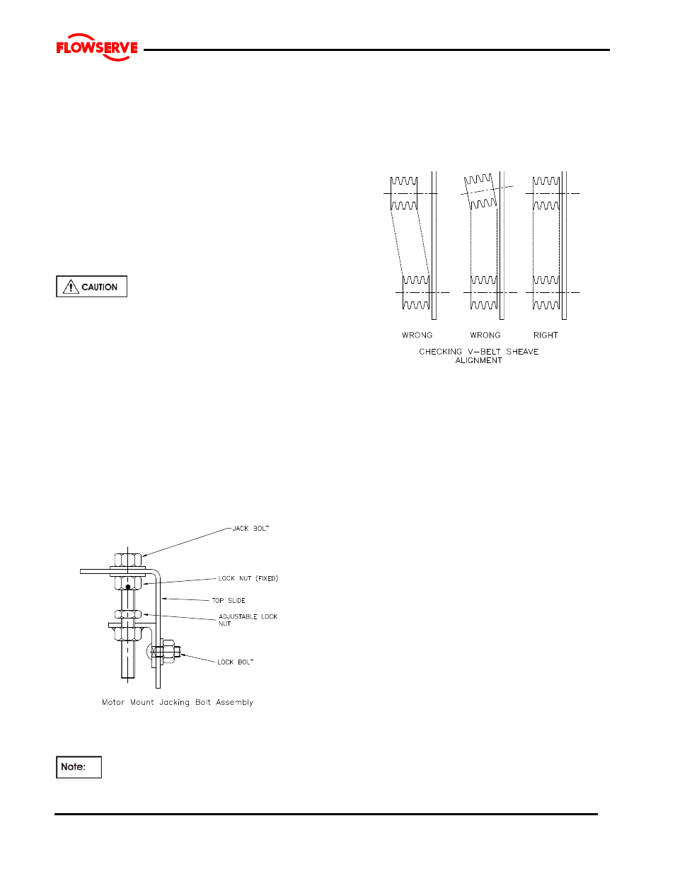
belt tension. Check the alignment of the pump and
driver sheaves with a taught string or straight edge. For
proper alignment and the sheave faces must be parallel
to each other and in line. Adjustments are made by
slackening the belts and moving the sheaves. Retighten
the drive or driver sheave then recheck. The procedure
may need to be repeated to get alignment as close as
possible.
When the sheaves are aligned that the shafts rotate
freely by hand and install safety guard.
Maintaining V-belt tension is the most
important rule of v-belt care.
V-belts that are too loose will cause excessive belt
wear or breakage.
V-belts are too tight will cause excessive loading on
the pump and motor bearings and could cause
overheating or reduced bearing lives.
Additional information is available from the
sheave and belt supplier.
The motor drive for sheave driven pumps is
frequently bolted to a motor support which is
constructed of fabricated steel. There are normally 4
adjustment bolts to alter the center distance between
the sheaves.
The adjustment procedure is as follows:
a) Release the lock bolts on each side of the motor
stand.
b) Release the locking nuts on the 4 jacking bolts. (2
on each bolt).
c) Turn the jacking bolts to move the motor out or in.
d) To install or remove belts it may be necessary to
move the motor 25mm (1”) towards the pump
frame.
e) Move the motor away from the pump frame to
tighten the belt tension.
f) Recheck the face of the sheaves and to ensure
that the faces are flat and in-line.
g) Lock the jacking bolts in place with the lock nuts.
h) Tighten the lock bolts on the side of the motor
mount.
i) Rotate the sheaves by hand to ensure that the
pump impeller is free to move.
j) Install the sheave/belt guard.