Flowserve MJ Slurry User Manual
Page 32
MJ SLURRY USER INSTRUCTIONS ENGLISH 71569294 - 02/08
Page 32 of 42
®
6.10.12 Casing
a) Smear a small amount of grease or anti-seize
compound over one face of the gasket [4590] and
place it on the stuffing box head [3200] with coated
face against flange.
b) Lift the casing and assemble to the pedestal. The
discharge may be orientated to various
configurations. Check the installation or GA drawing
for the proper position.
c) Secure into position. Ensure that the impeller is free
to rotate before tightening bolts.
d) Set the impeller front clearance in accordance with
instruction earlier in this section of the manual.
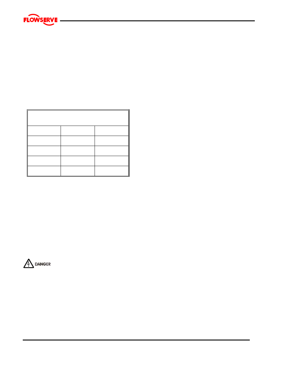
MINIMUM IMPELLER NUT
TIGHTENING TORQUE
FRAME
Ft.
lbs.
Nm.
1
100
140
2
300
400
3
300
400
4
550
750
a) Assemble the mechanical seal gland plate and
gasket and fasten using gland studs [6572]. Secure
with nuts [6521] and tighten each by hand. Further
tighten the nuts in accordance with Table in 6.6.
Rotate the shaft to ensure that it turns freely without
rubbing or binding.
b) Re-assemble the rotating element into the casing.
Do not adjust the thrust bearing housing.
c) Set the deflector [2540] at the line bearing cover
[3260.1] so that they do not contact when the shaft
is rotated. Lock in place with the setscrews
provided.
6.11 Impeller axial clearance adjustment
NEVER ATTEMPT TO CHANGE THE
CLEARANCE WHEN THE PUMP IS RUNNING.
If the coupling has limited axial adjustment capability,
the pump and driver must be uncoupled prior to
adjusting the clearance in order to permit free
movement.
a) Loosen the two setscrews retaining the deflector
[2540] and check that the deflector is free to
move axially on the shaft.
b) Loosen the thrust bearing housing jam nuts and
back off the three jacking screws at least 1.5 mm
(0.060 inch).
c) Move rotor towards the wear plate [1915.1] by
tightening the three hold-down capscrews evenly
and uniformly until the impeller [2200] just
touches the wear plate. Rotating the shaft and
stopping the forward motion at the first sign of
rubbing can best establish this. If the shaft
cannot be rotated, back off the bearing housing
with the jacking screws until a just detectable rub
is obtained. Check that the gap between the two
machined faces of thrust bearing housing [3240]
and the bearing frame [3130] are parallel within
0.003 inch (0.076 mm). Adjust the jackscrews
and hold down capscrews as required to achieve
this parallelism. When impeller [2200] just
touches wear plate [1915.1] and thrust bearing
housing [3240] is parallel to the bearing frame
[3130] the axial clearance between the impeller
and wear plate is zero.
6.11.1 Option1
a) Place a dial indicator, set to end of shaft [1110]
or on housing [3240] face.
b) Set indicator reading to zero (0).
c) Note required impeller clearance.
6.11.2 Option 2
a) Measure and record the axial gap between the
thrust bearing housing flange and bearing frame
end face. Determine the required impeller axial
running clearance from Section I and add this to
the above measurement to establish the required
gap setting.
6.11.3
a) Loosen the thrust bearing housing hold down
capscrews slightly and tighten the jackscrews.
Until the required dial indicator reading (6.11.1)
or housing gap reading (6.11.2) is achieved.
b) Alternately and gradually tighten the hold down
capscrews and jackscrews until the required gap
setting is achieved at each hold down capscrew
location. Note that the gap at each jackscrew will
be slightly larger as a result of minor elastic
distortion of the thrust bearing housing flange
caused by the high pre-load forces. The gap
setting at any set of screws must be the same
within 0.003 inch [0.076 mm). Careful attention
to this procedure will help ensure long thrust
bearing life.
c) While preventing the jackscrews from rotating,
tighten the jam nuts to lock them in position.
d) Adjust the axial position of the deflector [2540] so
that it is clear of the line bearing cover [3260.1]
by approximately 0.030 inch (0.75 mm) and
tighten the setscrews firmly. Excessive
tightening may mar the shaft.
e) Manually rotate the shaft to ensure that there is
no rubbing or binding.
f) On belt driven units, adjust the pump or driver
sheave to maintain belt alignment. (Refer to