Flowserve ME User Manual
Page 19
ME USER INSTRUCTIONS ENGLISH 71576287 - 02/13
Page 19 of 36
flowserve.com
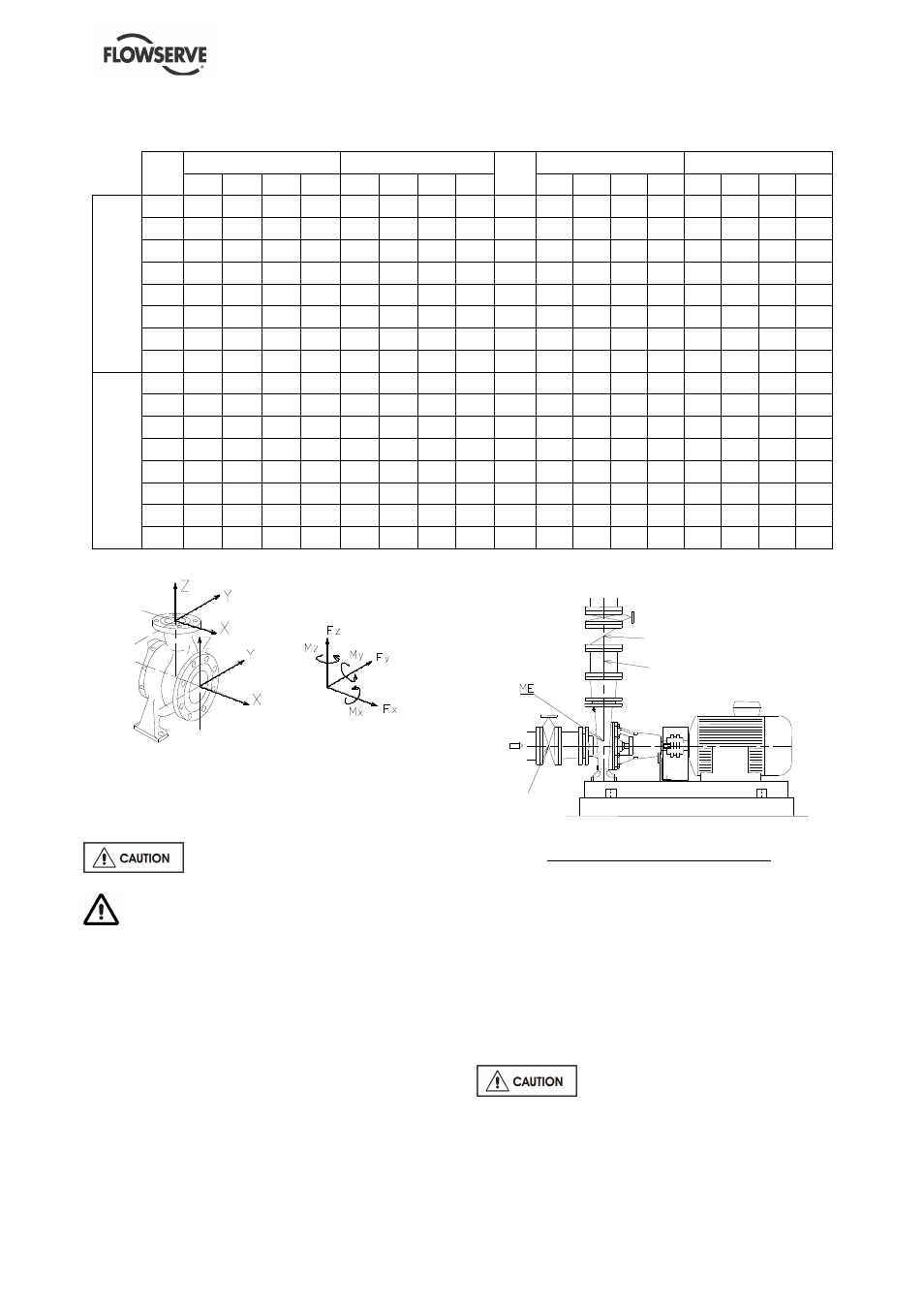
DN
Flange
Forces (daN)
Moments (m.daN)
DN
Flange
Forces (lbf)
Moments (lbf.ft)
Fy
Fz
Fx
∑
∑
∑
∑
F
My
Mz
Mx
∑
∑
∑
∑
M
Fy
Fz
Fx
∑
∑
∑
∑
F
My
Mz
Mx
∑
∑
∑
∑
M
V
e
rt
ic
a
l
d
is
c
h
a
rg
e
150
160
200
180
310
45
60
80
110
6"
360
450
405
698
332
443
591
812
200
215
265
240
415
85
100
125
180
8"
484
596
540
934
627
738
923 1329
250
270
335
300
520
125
145
180
260
10"
608
754
675 1170 923 1070 1329 1919
300
320
400
360
625
170
200
240
355
12"
720
900
810 1406 1255 1476 1772 2621
350
375
465
420
730
220
255
310
455
14"
844 1046 945 1643 1624 1882 2288 3359
400
430
530
480
835
275
320
390
570
16"
968 1193 1080 1879 2030 2362 2879 4208
450
485
600
540
940
340
390
480
705
18"
1091 1350 1215 2115 2510 2879 3543 5204
500
540
665
600
1040 410
470
580
850
20"
1215 1496 1350 2340 3027 3470 4282 6275
H
o
ri
z
o
n
ta
l
s
u
c
ti
o
n
,
150
180
160
200
315
45
60
80
110
6"
405
360
450
709
332
443
591
812
200
240
215
265
415
85
100
125
180
8"
540
484
596
934
627
738
923 1329
250
300
270
335
520
125
145
180
260
10"
675
608
754 1170 923 1070 1329 1919
300
360
320
400
625
170
200
240
355
12"
810
720
900 1406 1255 1476 1772 2621
350
420
375
465
730
220
255
310
455
14"
945
844 1046 1643 1624 1882 2288 3359
400
480
430
530
835
275
320
390
570
16"
1080 968 1193 1879 2030 2362 2879 4208
450
540
485
600
940
340
390
480
705
18"
1215 1091 1350 2115 2510 2879 3543 5204
500
600
540
665
1040 410
470
580
850
20"
1350 1215 1496 2340 3027 3470 4282 6275
Forces and moments values are applied to the
whole flanges and not flange-by-flange. For their
sharing out on the pump flanges, refer to standard
NFCR 13 931.
Ensure piping and fittings are flushed
before use.
Ensure piping for hazardous liquids is
arranged to allow pump flushing before removal of
the pump.
4.5.2 Suction piping
4.5.2.1 Design of a flooded suction line
The suction line must be as short and direct as
possible, never mount an elbow directly on the inlet
flange of the pump.
Non-return valve
Valve
Continuous
flow valve
Flooded suction configuration
a) Avoid sharp elbows or sudden narrowing. Use
convergent
≤
20° (total angle).
b) Arrange the piping so that there are no air
pockets (no bulges).
c) If high points cannot be avoided in suction line,
provide them with air relief cocks.
d) If a strainer is necessary, its net area should be
three or four times the area of the suction pipe.
e) If an inlet valve is necessary, choose a model
with direct crossing.
Do not tighten flanges before the final
check (see § 4.5.4).