6 piping – Flowserve WPG IDP User Manual
Page 13
WPG and WPH USER INSTRUCTIONS ENGLISH 26999969 10-12
Page 13 of 40
flowserve.com
Graph based on the assumptions that:
1)
Operating temperature rise of the motor frame is
50
C.
2)
Packing piece/motor stool is not affected.
Operation:
a)
Enter graph at base to shaft centre line height
b)
Read line for frame material
c)
Set motor shaft and coupling LOW by figure on
left-hand side
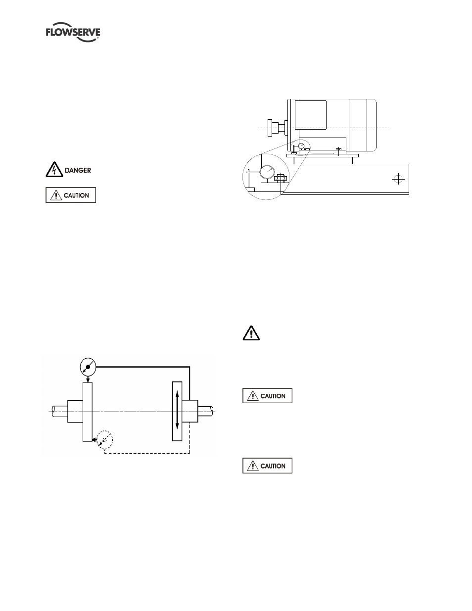
4.5.2 Alignment methods
Pump and driver must be isolated
electrically and the half couplings disconnected
.
The alignment MUST be checked.
Although the pump will have been aligned at the
factory, it is most likely that this alignment will have
been disturbed during transportation or handling.
Align the motor to the pump, not the pump to the
motor.
Alignment is achieved
by adding or removing shims
from under the motor feet and also moving the motor
horizontally as required. In some cases, where the
alignment cannot be achieved, it will be necessary to
move the pump before recommencing the above
procedure.
For couplings with narrow flanges, use a dial indicator
gauge as shown. The alignment values are
maximums for continuous service.
Permissible misalignment limits at working
temperature:
Parallel alignment
-
0.25 mm (0.010 in.) TIR maximum
Angular alignment
- 0.3 mm (0.012 in.) TIR maximum for
couplings not exceeding 100 mm (4 in.)
flange diameter
-
0.5 mm (0.020 in.) TIR maximum for
couplings over 100 mm (4 in.) diameter
When checking parallel alignment, the total indicator
read-out (TIR) shown is twice the value of the actual
shaft displacement.
4.5.3 Check for soft foot
This is a check to ensure that there is no undue
stress on the driver holding down bolts; due to non-
level baseplate or twisting. To check, remove all
shims and clean surfaces and tighten down driver to
the baseplate. Set a dial indicator as shown in sketch
and loosen off the holding down bolt while noting any
deflection reading on the dial test indicator - a
maximum of 0.05 mm (0.002 in.) is considered
acceptable but any more will have to be corrected by
adding shims. For example, if the dial test indicator
shows the foot lifting 0.15 mm (0.006 in.) then this is
the thickness of shim to be placed under that foot.
Tighten down and repeat the same procedure on all
other feet until all are within tolerance.
Complete piping as below and see sections 4.7,
Final shaft alignment check, up to and including
section
5, Commissioning, startup, operation and shutdown,
before connecting driver and checking actual rotation.
4.6 Piping
Protective covers are fitted to the pipe
connections to prevent foreign bodies entering during
transportation and installation. Ensure that these
covers are removed from the pump before connecting
any pipes.
4.6.1 Suction and discharge pipework
Never use pump as a support for piping.
In order to minimize friction losses and hydraulic
noise in the pipework it is good practice to choose
pipework that is one or two sizes larger than the
pump suction and discharge. Typically main
pipework velocities should not exceed 2 m/s (6 ft/sec)
suction and 3 m/s (9 ft/sec) on the discharge.