3 direction of rotation, 4 guarding, 5 priming and auxiliary supplies – Flowserve WPG IDP User Manual
Page 17: 6 starting the pump, 7 running the pump, Direction of rotation (5.3), Guarding (5.4), Priming and auxiliary supplies (5.5), Running the pump (5.7), Starting the pump (5.6)
WPG and WPH USER INSTRUCTIONS ENGLISH 26999969 10-12
Page 17 of 40
flowserve.com
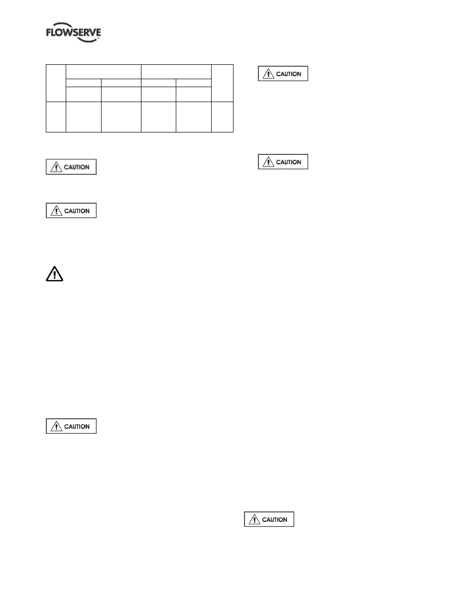
5.2.3 Bearing sizes and oil capacities
F
ra
m
e
si
ze
Integral and 2 piece
grease lubricated frames
Heavy duty oil lubricated
bearings
A
pp
ro
x.
oi
l
ca
pa
ci
ty
Pump end
Drive end
Pump end Drive end
Ball
bearing
Ball
bearing
Roller
bearing
Back-to-
back pair
1
2 & 3
4
5
6206 Z-OO
6309 Z-OO
6311 Z-OO
6314 Z-OO
6206 ZNR-OO
6309 ZNR-OO
6311 ZNR-OO
6314 ZNR-OO
NU 206 C3
NU 309 C3
NU 311 C3
Not available
T206 BG
7309 BG
7311 BG
Not available
0.6 L
0.8 L
1.0 L
1.2 L
NB The bearing sizes do not constitute a purchasing specification.
5.3 Direction of rotation
Serious damage can result if the
pump is started or run in the wrong direction of
rotation. Ensure the pump is given the same rotation
as the pump direction arrow.
If maintenance work has been carried
out to the site's electricity supply, the direction of
rotation should be re-checked as above in case the
supply phasing has been altered.
5.4 Guarding
Guarding is supplied fitted to the pump set.
In member countries of the EU and EFTA, it is a legal
requirement that fasteners for guards must remain
captive in the guard to comply with the Machinery
Directive 2006/42/EC. When releasing such guards,
the fasteners must be unscrewed in an appropriate
way to ensure that the fasteners remain captive.
Whenever guarding is removed or disturbed ensure
that all the protective guards are securely refitted
prior to start-up.
5.5
Priming and auxiliary supplies
5.5.1 Filling and priming
Ensure inlet pipe and pump casing is
completely full of liquid before starting continuous
duty operation.
Priming may be carried out with an ejector, vacuum
pump interceptor or other equipment, or by flooding
from the inlet source.
When in service, pumps using inlet pipes with foot
valves may be primed by passing liquid back from the
outlet pipe through the pump.
5.6 Starting the pump
a)
Ensure flushing and/or cooling/
heating liquid supplies are turned ON, before
starting pump.
b)
CLOSE the outlet valve.
c)
OPEN all inlet valves.
d)
Prime the pump.
e)
Start motor and check the outlet pressure.
f) If the pressure is satisfactory, SLOWLY open the
outlet valve.
g)
Do not run the pump against a
closed valve for more than 10 seconds.
h) If NO pressure, or LOW pressure, STOP the
pump. Refer to section 7, Faults; causes and
remedies, for fault diagnosis.
5.7 Running the pump
5.7.1 Pumps fitted with packed glands
If the pump has a packed gland there must be some
leakage from the gland. Gland nuts should initially be
finger-tight only. Leakage should take place soon
after the stuffing box is pressurised.
If no leakage takes place stop the unit, take out the
packing and repack to avoid the packing overheating. If
overheating takes place the pump should be stopped
and allowed to cool. before being re-packing. When
the pump is re-started it should be checked to ensure
leakage is taking place at the packed gland.
If hot liquids are being pumped it may be necessary
to slacken the gland nuts to achieve leakage.
The pump should be run for ten minutes with steady
leakage and the gland nuts tightened by 10 degrees
at a time until leakage is reduced to an acceptable
level, normally 30 to 120 drops per minute. Bedding
in of the packing may take another 15 minutes.
5.7.2 Pumps fitted with mechanical seal
Mechanical seals require no adjustment. Any slight
initial leakage will stop when the seal is run in. Seals
will always have leakage emission from the boundary
film edge in operation.
Before
pumping dirty liquids it is advisable, if possible,
to run the pump in using clean liquid to safeguard the
seal face.
For external flush or quench, this
should be started before the pump is run and allowed
to flow for a period after the pump has stopped.