Flowserve WPG IDP User Manual
Page 23
WPG and WPH USER INSTRUCTIONS ENGLISH 26999969 10-12
Page 23 of 40
flowserve.com
e)
Set the seal to the same position as marked when
dis-assembling the unit or refer to manufacturer's
instructions to position the mechanical seal
rotating elements on the shaft or sleeve.
f)
Tighten any drive screws in the seal drive collar.
g)
For precise compression most cartridge seals
should be set after complete pump assembly.
h)
Refit the seal plate and check that the seal is not
over-compressed or locked up solid.
i)
Fit new casing gasket and refit the complete
stuffing box cover/bearing housing unit to the
pump casing. Coat the screws with anti-galling
compound and tighten into casing.
6.9.4 Rotary oil seals
a)
Oil lip seals are not totally leak free devices and oil
leaking from a bearing housing can be visually
unpleasant in a clean pump room. Very careful
fitting practice for lip seals is therefore essential.
Particular attention must be paid to protecting the
seal from keyways by using shimming or tape and
careful handling of the shaft to avoid even fine
longitudinal scratches.
b)
Perfectly assembled oil seals can have a leakage
rate from almost zero to 40 mg/hr. This is
equivalent to approximately 2 drops per hour and
at this rate the constant level oiler would need
filling only once every 6 months.
c)
Fit oil seal carefully into position and refit the drive
side bearing cover and screws and tighten up.
d) Refit coupling key and pump half coupling using
heat, if necessary, to facilitate fitting. Do not
hammer the pump half coupling onto the shaft as
this will cause loading and damage to the bearings.
e)
Rotate pump shaft by hand to check for freedom
of rotation.
6.9.5 Refit to baseplate
a)
Refit pump to baseplate and check coupling
alignment as described in section 4.7, Final shaft
alignment check.
b)
Refit all safety guards and ensure all other items
have been re-attached and all fasteners tightened.
as section 6.6, Fastener torques,
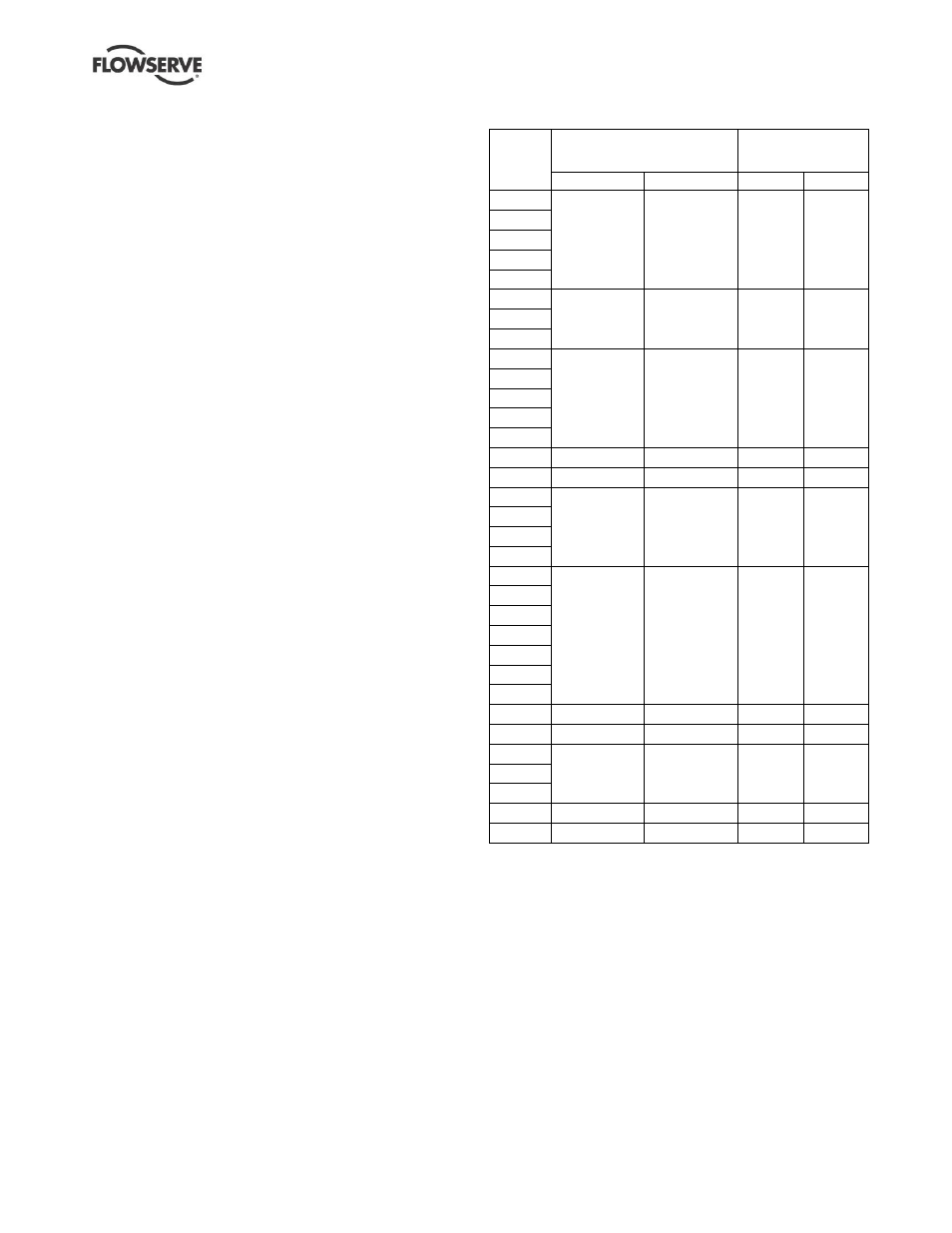
6.9.6 Wear ring clearances
Pump
size
Impeller hub diameter
(mm)
Diametral ring or
casing clearance
(mm)
Front
Back
Front
Back
65-100
82.54/82.45
82.54/82.45
0.64/0.4
0.64/0.46
50-125
50-160
40-200
40-250
32-125
70.54/70.47
70.75/70.47
0.60/0.46
0.60/0.4
32-160
32-200
65-125
93.54/93.45
93.54/93.4
0.64/0.46 0.64/0.46
65-160
50-200
50-250
50-315
80-125
111.47/111.38
93.54/93.45
0.71/0.53 0.64/0.46
25-161
55.54/55.47
55.54/55.47
0.60/0.46 0.60/0.46
80-160
111.47/111.38
111.47/111.38 0.71/0.53 0.71/0.53
65-200
65-250
65-315
100-160
152.47/152.37 152.47/152.37 0.67/0.53 0.67/0.53
100-200
100-250
125-250
100-315
125-315
100-400
125-225 168.10/168.00 168.10/168.00 0.80/0.60 0.80/0.63
125-400 184.00/183.90 184.00/183.90 0.71/0.53 0.71/0.53
150-250
209.40/209.30 209.40/209.30 0.80/0.60 0.80/0.63
150-315
150-400
200-401 269.24/269.14 269.24/269.14 0.85/0.65 0.85/0.65
150-500 219.47/219.37 219.47/219.37 0.73/0.53 0.73/0.53