Flowserve Chemstar standard User Manual
Page 13
CHEMSTAR USER INSTRUCTIONS ENGLISH 71569185 02-10
Page 13 of 44
flowserve.com
•
Prevent excessive external pipe load
•
Never draw piping into place by applying force to
pump flange connections
•
Do not mount expansion joints so that their force,
due to internal pressure, acts on the pump flange
Ensure piping and fittings are flushed
before use.
Ensure piping for hazardous liquids is arranged
to allow pump flushing before removal of the pump.
4.6.2 Suction piping
a) The inlet pipe should be one or two sizes larger
than the pump inlet bore and pipe bends should
be as large a radius as possible.
b) On suction lift the piping should be inclined up
towards the pump inlet with eccentric reducers
incorporated to prevent air locks.
c) On positive suction, the inlet piping must have a
constant fall towards the pump.
d) The pipe next to the pump should be the same
diameter as the pump suction and have a minimum
of two pipe diameters of straight section between
the elbow and the pump inlet flange. Where the
NPSH margin is not large, it is recommended that
the straight pipe is 5 to 10 times the pipe diameter.
(See section 10.3, Reference 1.) Inlet strainers,
when used, should have a net 'free area' of at least
three times the inlet pipe area.
e) Fitting isolation and non-return valves will allow
easier maintenance.
f) Never throttle pump on suction side and never
place a valve directly on the pump inlet nozzle.
4.6.3 Discharge piping
A non-return valve should be located in the discharge
pipework to protect the pump from excessive back
pressure and hence reverse rotation when the unit is
stopped.
Fitting an isolation valve will allow easier maintenance.
4.6.4 Auxiliary piping
The connections that are to be piped
up will have been fitted with protective metal or
plastic plugs which will need to be removed.
4.6.4.1 Pumps fitted with packed glands
a) Packing is to be fitted before use.
b) A temporary PTFE lip seal may have been
installed against the face of the stuffing box for
shipping. If so, discard this lip seal and slide the
packing rings [4130] and lantern ring [4134] into
the stuffing box in the order shown.
c) Always stagger the end gaps of the packing by
90 degrees apart to ensure the best seal.
d) To speed installation of each ring, have an
assistant turn the pump shaft in the correct
direction. This movement will tend to draw the
rings into the stuffing box.
e) Lightly tighten the gland.
f) Final adjustments are covered in section 5.8,
Running the pump.
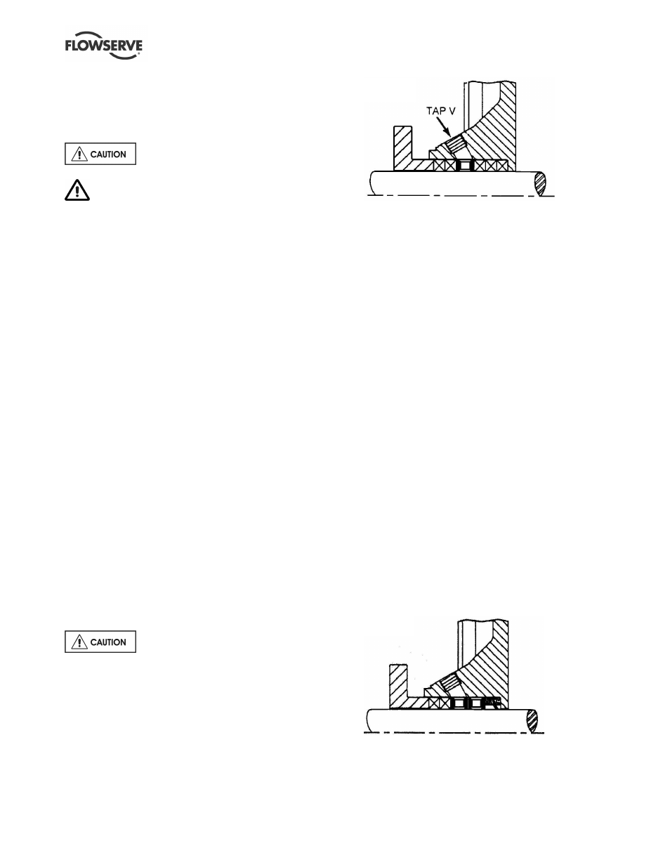
g) When suction pressure is below ambient
pressure and stuffing box head over total suction
head is less than 10 m (33 ft), it may be
necessary to feed gland packing with compatible
liquid to the pumpage to provide lubrication and
prevent the ingress of air. This is to be added
through tap V shown above. The pressure of the
feed liquid should be at least 1 bar (14.5 psi)
above the stuffing box pressure, regulated to a
flow rate of 0.25 to 0.5 m
3
/h (1 to 2 USgpm). At
lower speeds, grease lubrication may be used
when compatible with the pumpage. In non-
abrasive applications, where the pumpage itself
is sufficient to lubricate the packing without an
external pipeline, tap V should be plugged.
h) When a special abrasive liquid packing
arrangement is specified, the installation
procedures are the same as the standard packing
with the following exceptions. The special lip seal
is installed first, followed by two seal cage
assemblies, then two of the packing rings provided
as shown below. An external compatible liquid
source line should be connected to tap V, in the top
of the stuffing box.