Flowserve Chemstar standard User Manual
Page 27
CHEMSTAR USER INSTRUCTIONS ENGLISH 71569185 02-10
Page 27 of 44
flowserve.com
Proceed by removing the rear cover evenly in
small increments around the circumference of the
impeller cover.
e) For Group C400 pumps remove the capscrews
[6570.5] that hold the rear cover [1220.1] to the
bearing housing [3200] flange and slide the cover
[1220.1] out of the repeller cover [1220.3].
f) The repeller [2200.1] is now exposed and should
be free to slide from the shaft once the nose cone
had been removed. Should it be stuck, the
repeller can be pried off by using 2 screwdrivers
wedged between the repeller [2200.1] and the
repeller cover [1220.2].
6.9 Examination of parts
Used parts must be inspected before
assembly to ensure the pump will subsequently run
properly. In particular, fault diagnosis is essential to
enhance pump and plant reliability.
6.9.1 Casing, rear cover and impeller
Inspect for excessive wear, pitting, corrosion, erosion
or damage and any sealing surface irregularities.
Replace as necessary.
6.9.2 Shaft and sleeve (if fitted)
Replace if grooved or pitted. With the bearing
mounting diameters (or bearing outer) supported by
V-blocks, check that the shaft runouts are within
0.025 mm (0.001 in.) at the coupling end and
0.050 mm (0.002in.) at the sleeve end.
6.9.3 Gaskets and O-rings
After dismantling, discard and replace.
6.9.4 Bearings
It is recommended that bearings are not re-used after
any removal from the shaft.
6.9.5 Bearing isolators, labyrinths or lip seals
(if fitted)
The lubricant, bearings and bearing housing seals
are to be inspected for contamination and damage. If
oil bath lubrication is utilised, these provide useful
information on operating conditions within the bearing
housing. If bearing damage is not due to normal
wear and the lubricant contains adverse
contaminants, the cause should be corrected before
the pump is returned to service.
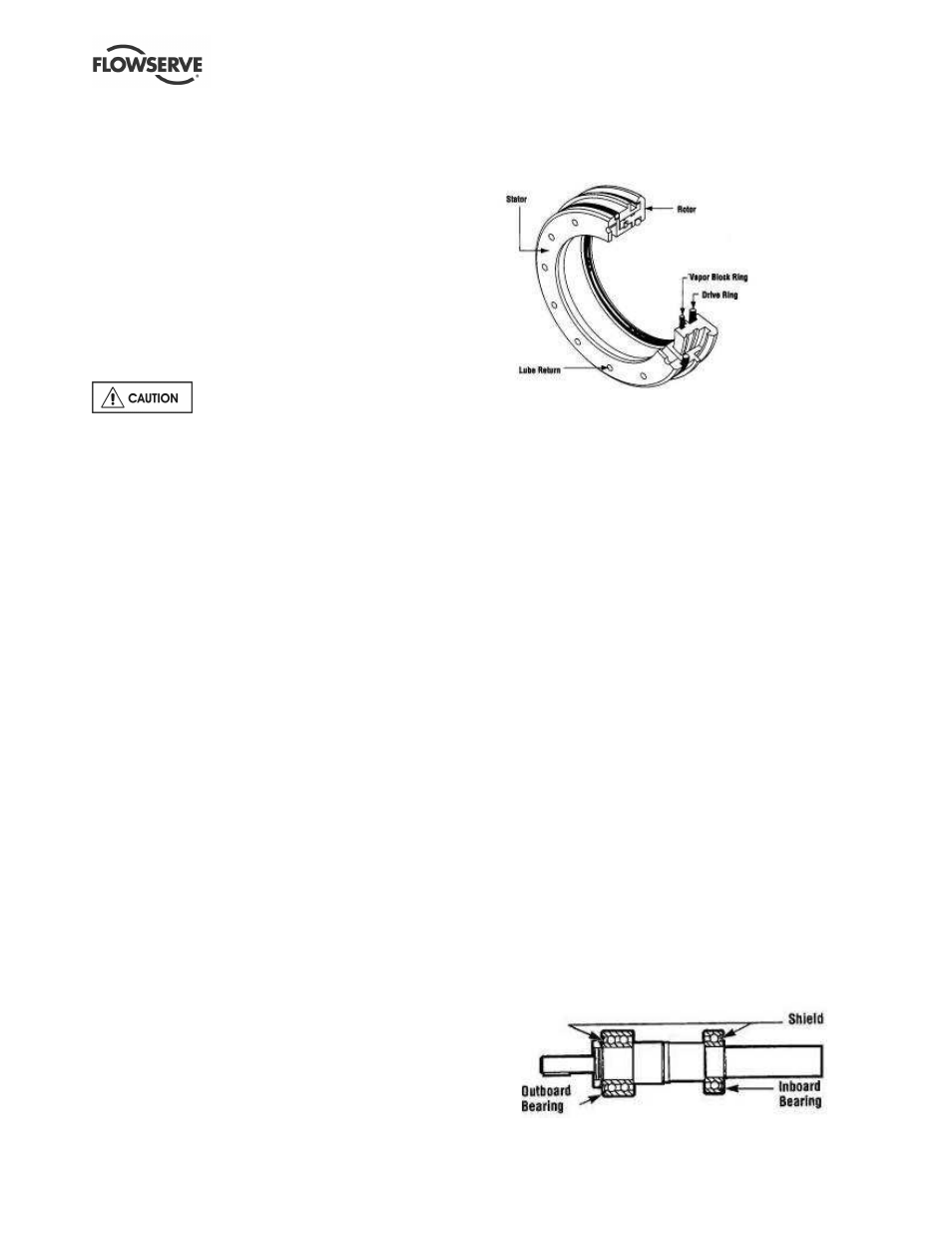
Labyrinth seals and bearing isolators are not intended to
be separated from the bearing housing/adapter/ bearing
carrier unless being replaced. One example of a variety
of approved isolators that may be fitted is shown.
These should be inspected for damage but are normally
non-wearing parts and can be re-used. Check O-rings
and external return passages. O-rings may require
replacement when a labyrinth seal has been removed.
Replacement O-ring sets are available for most designs.
Bearing seals are not totally leak free devices.
Oil from these may cause staining adjacent to the
bearings.
6.9.6 Bearing housing and carrier
Inspect the bearing carrier circlip groove. Ensure it is
free from damage and that housing lubrication
passages are clear. Replace grease nipples or the
filter breather (where fitted), if damaged or clogged.
On oil lubricated versions, the oil level sight glass
should be replaced if oil stained.
6.10 Assembly
To assemble the pump consult the sectional
drawings. See section 8, Parts lists and drawings.
Ensure threads, gasket and O-ring mating faces are
clean. Apply thread sealant to non-face sealing pipe
thread fittings.
6.10.1 Bearing housing and rotating element
assembly
a) Clean the inside of the bearing housing, bearing
carrier and bores for bearings.
b) Attach bearing housing support foot.
c) Before replacing bearings, the shaft [2100]
should be carefully inspected. If the shaft is in
good condition, new inboard [3011] and outboard
bearings [3013] should be installed onto the
shaft, otherwise use a new shaft.
d) If the bearing housing is equipped with
regreasable bearings, the shields should be
oriented facing outwards as shown below: