Flowserve Chemstar standard User Manual
Page 29
CHEMSTAR USER INSTRUCTIONS ENGLISH 71569185 02-10
Page 29 of 44
flowserve.com
p) The bearing housing lip seals [4310.1 and 4310.2]
are a double lip type and the cavity between the two
lips should be packed with grease.
q) Fit O-ring on the bearing carrier. Lightly lubricate
the bearing carrier bore and O-ring.
r) Ensure the shaft keyway edges are free of burrs.
During installation, use shimming or tape over the
keyway to avoid damaging the drive side bearing
seals.
s) Slide the bearing carrier [3240] onto the shaft/
bearing assembly and insert bearing inner snap
ring [2530] or locking ring [3240.1] depending
upon size and bearing configuration.
t) Check shaft for free rotation.
u) Fit the pump side labyrinth into the bearing
housing ensuring if a single drain hole that it
faces the bearing and is at the 6 o'clock position.
v) Install the shaft assembly into the bearing housing.
w) Fit the bearing carrier screws.
x) Press inboard deflector [2540] onto shaft where
applicable (lip seals fitted). These should be set
0.5 to 1 mm (0.02 to 0.04 in.) off the lip seal and
must not contact the lip seal or bearing housing.
y) Temporarily fit the rear cover with the correct
topmost position.
6.10.2 Rear cover and seal assembly - standard
pump
a) Extreme cleanliness is required. The sealing
faces and shaft or sleeve surface must be free
from scratches or other damage.
b) Refer to section 6.11, Sealing arrangements, for
seal diagrams.
c) On non cartridge seals, carefully press the
component stationary seat into the mechanical
seal housing or cover, ensuring that the seating
ring is not deformed.
d) Where an anti-rotation pin is fitted ensure that
correct engagement with the slot is achieved.
e) Place any separate seal follower [4131] or the
cartridge seal assembly over the shaft.
f) Refer to manufacturer's instructions to position
the component or non-cartridge mechanical seal
rotating elements.
g) Tighten any drive screws in the seal drive collar.
For precise compression most cartridge seals
should be set after complete pump assembly.
h) Fit the rear cover into the bearing housing and
tighten all fasteners.
6.10.3 Gland packed stuffing box assembly
a) Assemble the gland packing into the stuffing box
housing before fitting on to the shaft.
b) Stagger the joints in the gland packing by 90
degrees to each other.
c) The lantern ring halves (if required) should be
positioned mid-way along the packing.
d) Position the gland squarely against the last ring
and tighten the gland nuts finger-tight only.
e) Install into bearing housing assembly and fit the
two screws to hold the cover in place.
f) Check that the shaft rotates freely.
6.10.4 Impeller assembly and setting
a) Fit a new O-ring [4610.1] into the impeller using a
small amount of grease to hold it in place.
b) Apply anti-galling compound (which does not
contain copper) to the impeller thread to help
subsequent removal.
c) Assemble impeller onto the shaft.
d) Fit a chain wrench or bolt a bar to the holes in the
coupling half, or fit a keyed shaft wrench directly
to the shaft, first removing the coupling.
Preferably clamp the bearing housing foot of the
subassembly to the work surface.
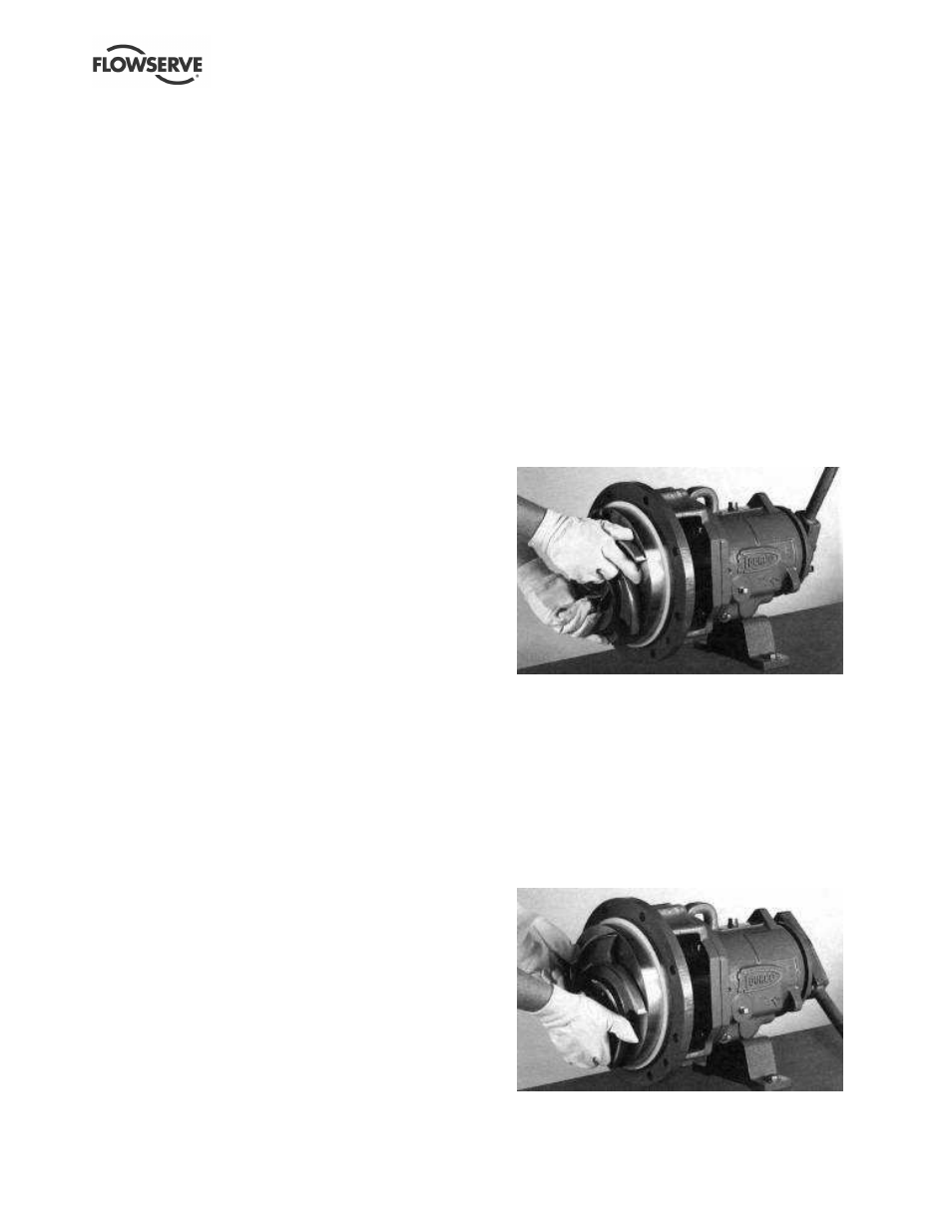
e) Tighten the impeller. Grasp the impeller firmly
with both hands (wear heavy gloves). Raise the
wrench above the workbench to the 1 o'clock
position by turning the impeller counter-clockwise
as viewed from the impeller end of the shaft.
This is the opposite direction of rotation to
disassembly.
f) Give the impeller a quick turn clockwise to strike
the wrench handle against the workbench
surface or a hard surface on the right hand side.
A few sharp raps in this way will tighten the
impeller to the correct level.