4 storage, 5 recycling and end of product life, 3 pump description 3.1 configurations – Flowserve NM User Manual
Page 12
NM USER INSTRUCTIONS ENGLISH 71576289 - 11/09
Page 12 of 48
2.4 Storage
Store the pump in a clean, dry
location away from vibration. Leave piping
connection covers in place to keep dirt and other
foreign material out of pump casing. Turn pump at
intervals to prevent brinelling of the bearings and
the seal faces, if fitted, from sticking.
Do not store pumps starting on the fan guard.
The pump may be stored as above for up to 6
months. Consult Flowserve for preservative
actions when a longer storage period is needed.
2.5 Recycling and end of product life
At the end of the service life of the product or its
parts, the relevant materials and parts should be
recycled or disposed of using an environmentally
acceptable method and local regulations. If the
product contains substances which are harmful to
the environment, these should be removed and
disposed of in accordance with current regulations.
This also includes the liquids and or gases in the
"seal system" or other utilities.
Make sure that hazardous substances or
toxic fluid are disposed of safely and that the
correct personal protective equipment is used. The
safety specifications must be in accordance with
the current regulations at all times.
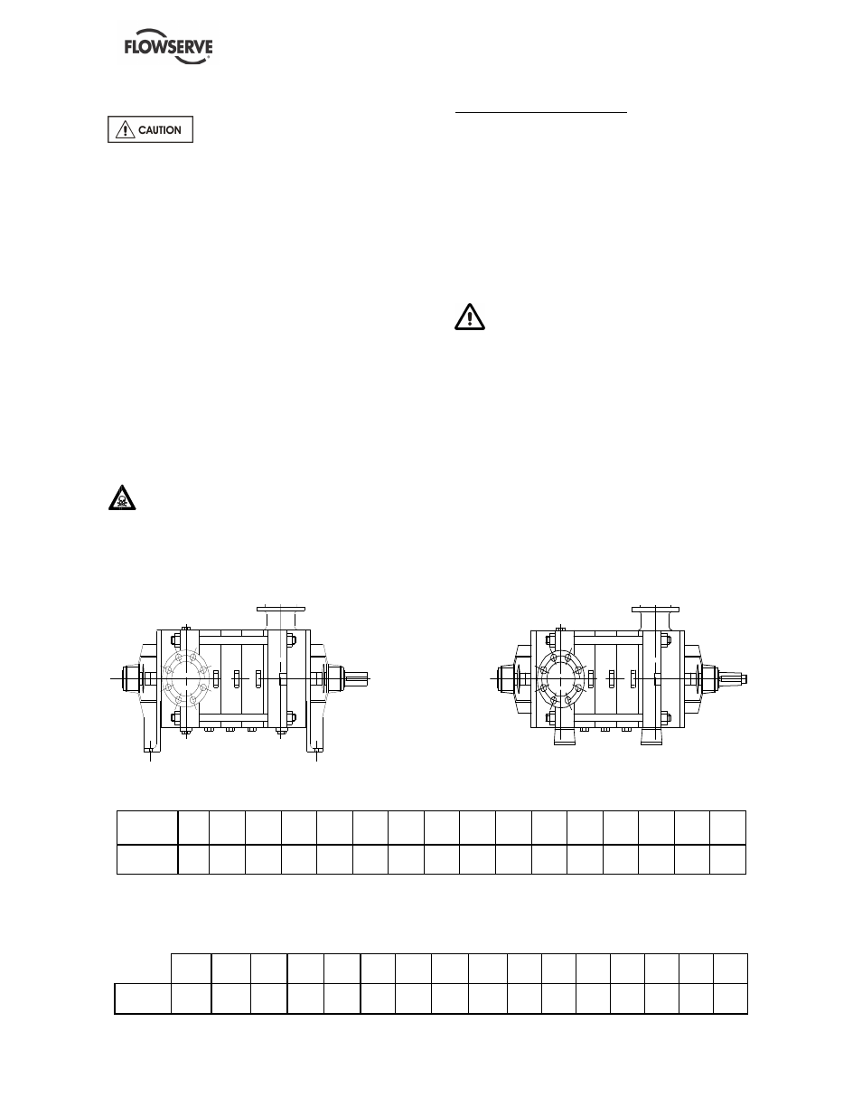
3 PUMP DESCRIPTION
3.1 Configurations
The multi-stage centrifugal pump is designed for
the pumping of cold water or all clear liquids which
are not solid and liquid mixtures, non-corrosive,
non-abrasive or non-explosive when in contact
with the pump motor unit and its working parts
(Important: for other liquids consult FLOWSERVE
for beforehand advice).
The NM type pump is a centrifugal, multi-stage,
single suction and radial joint plan pump.
The pump must be stored in a non-explosive,
ventilated location, sheltered from bad weather,
dust and vibrations.
The reliability of the delivered machine can only be
ensured if it is used according to the conditions
given in this manual. The maximum values
specified in this manual must never be exceeded.
•
Maximum working pressure at discharge
Lamellar
Cast Iron
32
NM
40
NM
50
NM
65
NM
80
NM
100
NM
125
NM
150
NM
200
NM
201
NM
102
NM
122
NM
152
NM
202
NM
252
NM
352
NM
Pressure
in bar
35
35
35
35
38
40*
60
40*
40*
45
25
25
30
35
40
40
* For cast iron with spheroidal graphite: 60 bars
•
Maximum working pressure at suction
32
NM
40
NM
50
NM
65
NM
80
NM
100
NM
125
NM
150
NM
200
NM
201
NM
102
NM
122
NM
152
NM
202
NM
252
NM
352
NM
Pressure
in bar
10
10
10
10
10
16
16
16
16
16
10
10
10
10
16
16