Flowserve ISC2 Dual metal bellows sea User Manual
Page 10
10
Figure 24
Figure 25
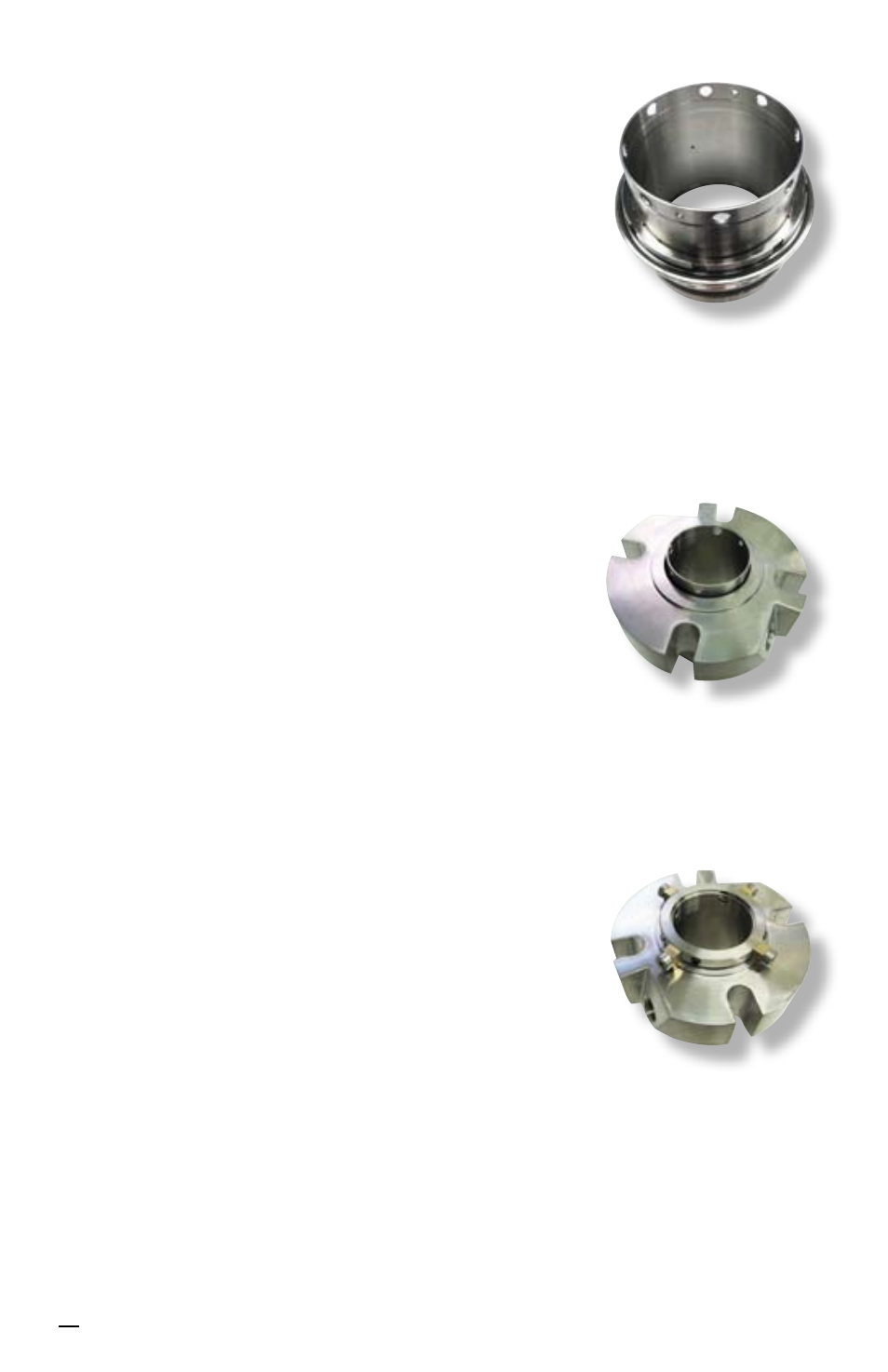
Figure 26
6.15 For sizes ≤ 2.750 inch (70 mm) insert the bellows
vibration dampener [183] into the rotating face
support. Make sure that the vibration dampener
is fully seated at the bottom of the rotating face
support. See Figure 24.
For sizes > 2.750 inch (70 mm)
install the O-ring
[76.1] into the bellows assembly.
6.16 Repeat steps 6.3 through 6.6 to assemble the
outboard bellows assembly [79.1] into the sleeve/
rotating face support assembly and outboard
stationary face O-ring [13.1], outboard vibration
dampeners [183.1] and [183] and outboard
stationary face [14.1] into the outer gland
assembly [11.1].
6.17 Place the outer gland assembly face down onto
the sleeve assembly. See Figure 25.
6.18 Thread set screws and quarter-dog set screws
in proper, equally spaced locations in drive collar
[58].
Note:
Some sizes > 2.750 inch (70 mm) do not
utilize quarter-dog set screws.
6.19 Install the drive collar [58] onto the sleeve
assembly [1]. The drive collar may need to be
rotated so that the set screws [57] line up with the
large holes and quarter-dog set screws [57.1] line
up with the two smaller holes.
6.20 Install the setting devices [103] and cap screws
[40] into the collar, engaging in the gland [11]. See
Figure 26.
6.21 Compress the collar to be even with the end of
the sleeve assembly. This will also compress
the gland and inner gland simultaneously. While