1 nomenclature – Flowserve ISC2 Dual metal bellows sea User Manual
Page 2
ISC2-BB
1.875
316 SS
Part references in this document are denoted in square parenthesis, e.g. [79]
Refer to the Bill of Material
for proper placement of material-specific
components.
Notes for sizes ≤ 2.750 inch (70 mm):
• Inboard and outboard bellows assemblies [79] and [79.1] are
interchangeable.
• Inboard and outboard stationary faces [14] are interchangeable.
• O-rings [76.1], [13.1], [76] and [13] are interchangeable.
Notes for sizes > 2.750 inch (70 mm):
• Inboard and outboard bellows assemblies [79] and [79.1] are
interchangeable.
• Inboard and outboard stationary faces [14] and [14.1] are not
interchangeable.
• O-rings [76.1] and [76] are interchangeable.
• O-rings [13.1] and [13] are interchangeable.
2
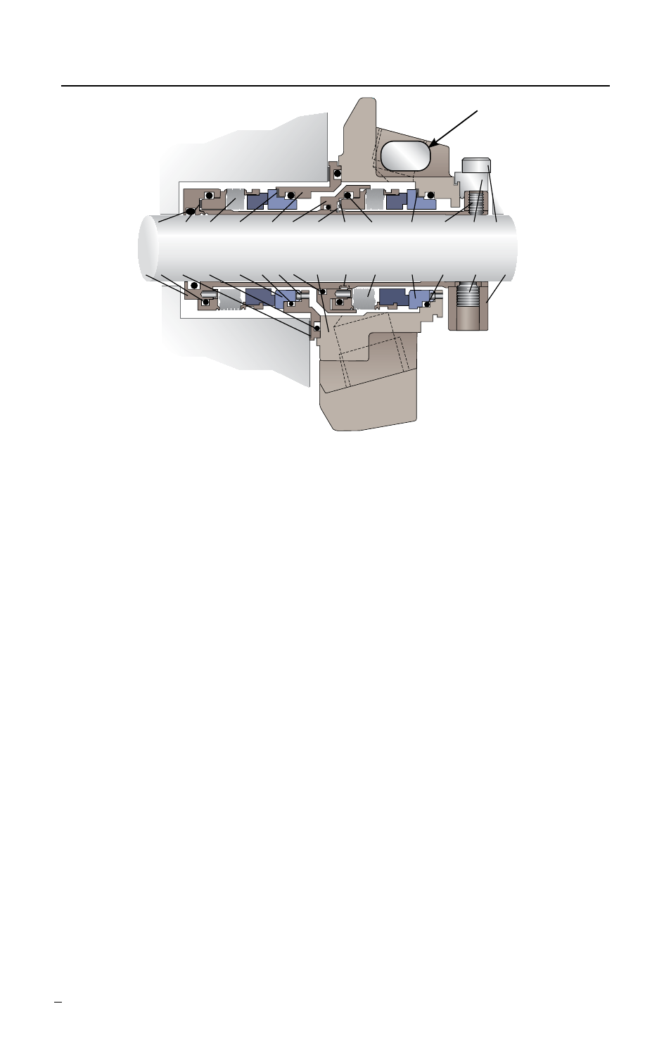
1 Nomenclature
19 183 79 183.1 11 99 111 183 76.1 183.1 57 103 40
1 76 18 18.1 14 13 5 71 11.1 5.1 79.1 14.1 13.1 57.1 58
Part Description
Ref.
1 Sleeve Assembly
5 Square-headed Pin
5.1 Drive Pin
11 Inner Gland
11.1 Outer Gland
13 Seat Gasket O-ring
13.1 Seat Gasket O-ring
14 Inboard Stationary Face
14.1 Outboard Stationary Face
18 Gland Gasket
18.1 Inner Gland O-ring
19 Sleeve Gasket O-ring
40 Cap Screw
57 Cup-point Set Screw
Figure 1
Sizes
≤
2.750 inch
(70 mm)
Sizes
>
2.750 inch
(70 mm)
Part
marking
sample
57.1 Quarter-dog Set Screw
58 Drive Collar
71 Rotating Face Support O-ring
76 Inboard Bellows O-ring
76.1 Outboard Bellows O-ring
79 Inboard Bellows Assembly
79.1 Outboard Bellows Assembly
99 Rotating Face Support
103 Setting Device
111 Snap Ring
183 Vibration Dampener
183.1 Bellows Vibration Dampener