Flowserve ISC2 Dual metal bellows sea User Manual
Page 9
9
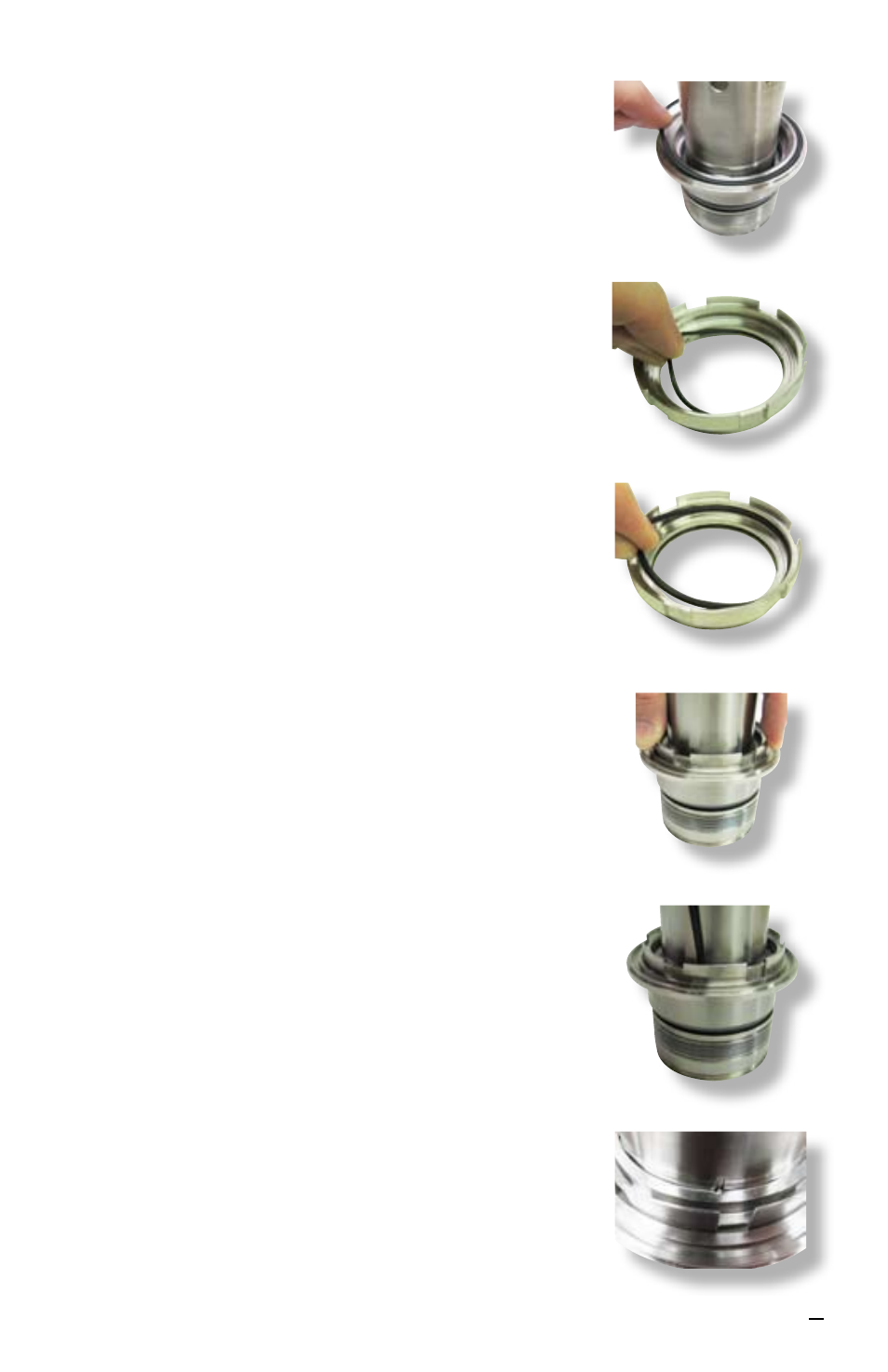
6.10 Install the inner gland O-ring [18.1] into the groove
on the inner gland. See Figure 18.
6.11 Place the rotating face support O-ring [71] in the
smallest diameter groove of the rotating face
support [99]. See Figure 19.
6.12 For sizes ≤ 2.750 inch (70 mm) place the outboard
bellows O-ring [76.1] in the O-ring surface of the
rotating face support, which is behind the surface
with two drive flats. See Figure 20.
6.13 Align the flats on the rotating face support with
the flats on the sleeve and slide the rotating face
support onto the sleeve with the pumping vanes
facing up. See Figure 21.
6.14 For sizes ≤ 2.750 inch (70 mm) install the snap
ring [111] onto the sleeve assembly into the sleeve
groove beneath the rotating face support.
Note
: Fully seating the rotating face support
[99] on the sleeve assembly [1] will require
compressing the bellows assembly [79] of the inner
seal by pressing down on the inner gland [11.1].
Make sure the snap ring is fully engaged in the
groove in the sleeve. See Figure 22.
For sizes > 2.750 inch (70 mm)
rotate the rotating
face support [99] to align the slots on the sleeve
with the slots on the inner diameter of the rotating
face support. Once the slots are aligned to form a
hole, insert the straight pins [5.1]. See Figure 23.
Figure 18
Figure 19
Figure 20
Figure 21
Figure 22
Figure 23