Flowserve ISC2 Dual metal bellows sea User Manual
Page 8
8
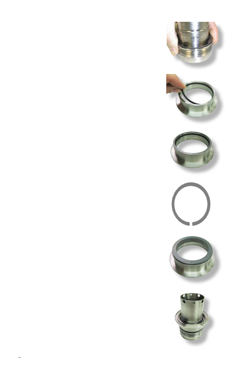
bellows assembly into place using finger pressure
only. See Figure 12.
For sizes > 2.750 inch (70 mm)
align the drive pin
on the sleeve with the drive slot on the bellows
assembly and press the bellows assembly into
place using finger pressure only.
Caution
: Do not over-compress the bellows
assembly.
6.4 Clean the sealing face of the bellows assembly
[79] to remove any dirt, dust, fingerprints, grease
or any other residue using alcohol on a clean cloth
or tissue.
6.5 Place the inboard stationary face O-ring [13] into
the inner gland [11]. See Figure 13.
6.6 For sizes ≤ 2.750 inch (70 mm) install the vibration
dampener [183.1] onto the inner gland surface
where the stationary face [14] will be installed. See
Figure 14.
For sizes > 2.750 inch (70 mm)
install the square-
headed pin [5] into the hole on the inner gland
where the stationary face [14] will be located. Cut
a 0.250 inch (6 mm) slot in the vibration dampener
[183]. See Figure 15. Install onto the inner gland
surface where the stationary face will be installed
with the slot positioned where the drive pin is
located.
6.7 For sizes ≤ 2.750 inch (70 mm) align the flats on
the inboard stationary face [14] with the flats on
the inside of the inner gland [11], and press the
stationary face in place using finger pressure only.
See Figure 16.
For sizes > 2.750 inch (70 mm)
ensure that the slot
on the stationary face [14] and the square-headed
pin [5] are aligned and install into the inner gland
[11] using finger pressure only.
6.8 Clean the sealing face of the stationary face [14]
to remove any dirt, dust, finger prints, grease or
any other residue using ethyl alcohol on a clean
cloth or tissue.
6.9 Place the inner gland assembly face down onto the
sleeve assembly. See Figure 17.
Figure 12
Figure 13
Figure 14
Figure 17
Figure 15
Figure 16