3 equipment checks, Check axial shaft travel figure 2 – Flowserve SLC Series Interseal User Manual
Page 3
3
2 Equipment Preparation for Mechanical Seal Installation
2.1 Follow plant safety regulations prior to equipment disassembly:
• lock out motor/driver and valves.
• wear designated personal safety equipment.
• relieve any pressure in the system.
• consult plant MSDS files for hazardous material regulations.
• vent and drain equipment before any work is performed in the
field or removed to a maintenance facility.
2.2 Disassemble and clean all equipment to allow access to seal installation area.
2.3 When converting from a packed stuffing box, replacement equipment parts may
be required such as taper bore covers, liners, and high efficiency impellers.
These items should specifically be designed for use with mechanical seals.
3 Equipment Checks
3.1 Radial and thrust bearings should be in new condition. If not, new ones should
be installed into the equipment.
3.2 The saddle fits of the bearing assembly should be checked for abnormal wear
and reconditioned if worn.
3.3 Ensure that all fit locations on the pedestal and adapter are clean and free from
burrs.
3.4 Ensure that the bearing assembly is mounted correctly (central and square) to
the pump pedestal and securely fastened.
3.5 Clean dried product, rust, and oils from the pump shaft or shaft sleeve. Remove
all burrs and sharp edges from the shaft and shaft sleeve including sharp edges
of keyways and threads.
3.6 Replace worn shaft or shaft sleeve. Ensure that the shaft or shaft sleeve has a
1.57 mm (0.062 inch) x 30 degree chamber on the leading edge to help prevent
O-ring damage during seal installation.
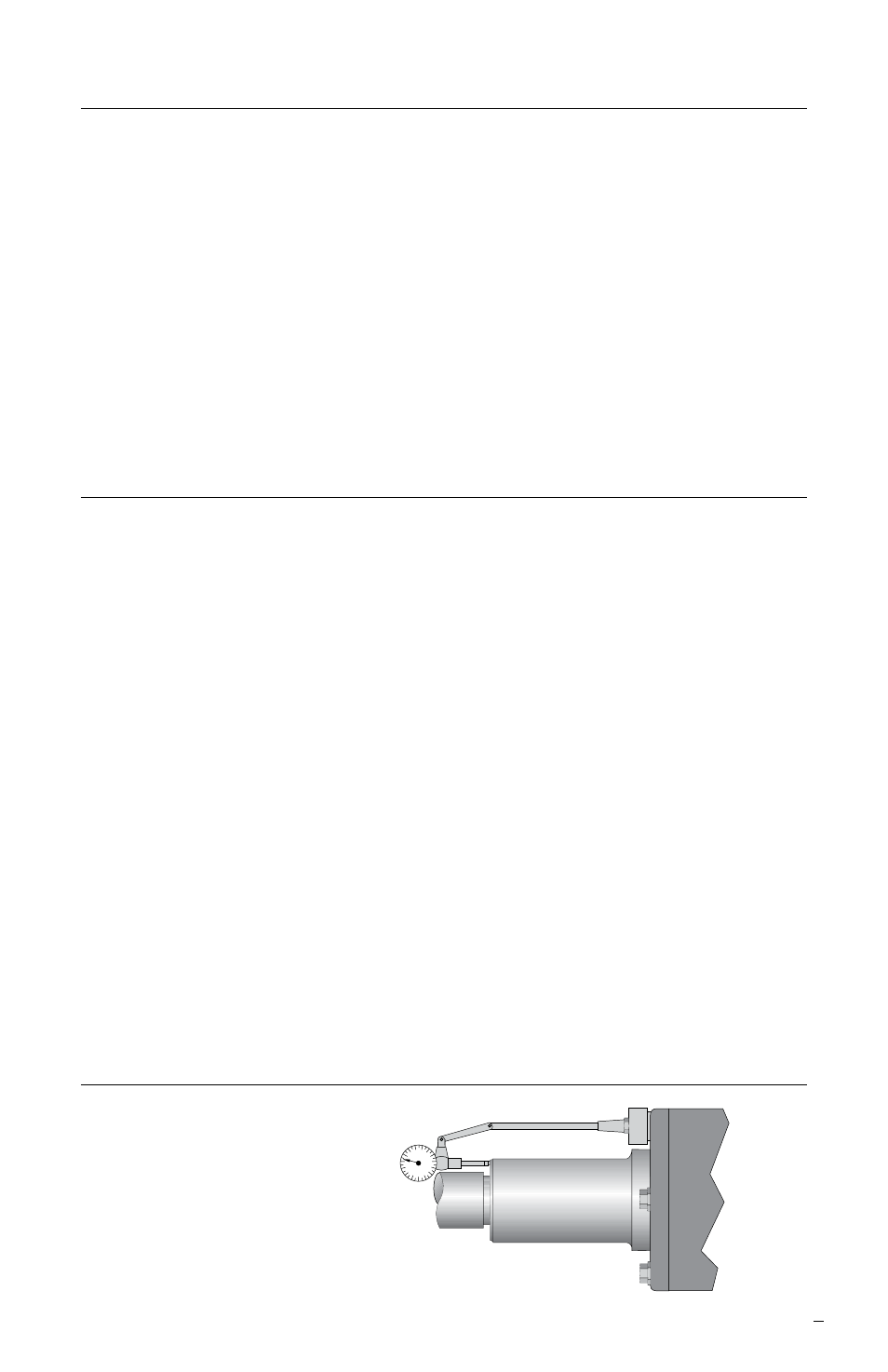
3.7 The axial end float of the equipment shaft must be set to the manufacturer’s
specifications. As a guide 0.05 mm (0.002 inch) per inch of shaft diameter to a
maximum of 0.40 mm (0.016 inch) FIM. See Figure 2. Addition of shims or ma-
chining adjustments to the bearing end cover may be required to limit end play.
Check Axial Shaft Travel Figure 2
0.38 mm (0.015 inch) FIM (TIR) Maximum
Acceptable Axial Movement