Check radial shaft deflection figure 3, 4 wet (impeller side) cartridge installation, Center adapter plate to shaft figure 4 – Flowserve SLC Series Interseal User Manual
Page 4
4
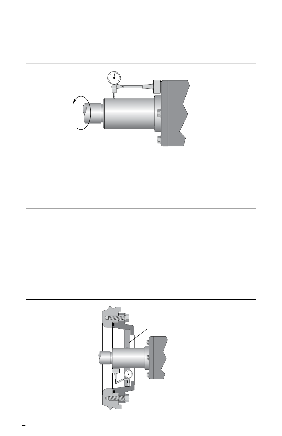
3.8 Shaft radial run out should be less than 0.13 mm (0.005 inch) FIM (TIR).
See Figure 3. Turn shaft 360° and observe the movement. Excessive
movement may indicate a bent or warped shaft that needs replacement.
Check Radial Shaft Deflection Figure 3
3.9 Make sure all seal housing bores, mounting surfaces, and fluid line connections
are clean and free of burrs and sharp edges that might damage secondary seal-
ing elements (O-rings, V-rings, or gaskets).
4 Wet (impeller side) Cartridge Installation
This section describes the installation of the seal cartridge from the wet or impeller
side of the equipment case. If your cartridge is designed to install from the dry or bear-
ing side of the equipment case, skip to section 5.
4.1 Bolt seal adapter plate to equipment case/pedestal (hand tighten only).
4.2 Locate the seal fit of the adapter to the shaft by use of a dial indicator or center-
ing jig. The equipment shaft must be concentric to the seal adapter bore to
within 0.25 mm (0.010 inch) FIM (TIR). See Figure 4. Seal life can vary with
improper alignment; poor shaft alignment will yield poor seal life.
Center Adapter Plate to Shaft Figure 4
Adapter to be Concentric with Shaft
within 0.25 mm (0.010 inch) FIM (TIR)
Centering Jig
0.13 mm (0.005 inch) FIM (TIR)
Maximum Acceptable Radial Run Out