Torque value chart n-m (ft-lb) figure 8 – Flowserve SLC Series Interseal User Manual
Page 6
6
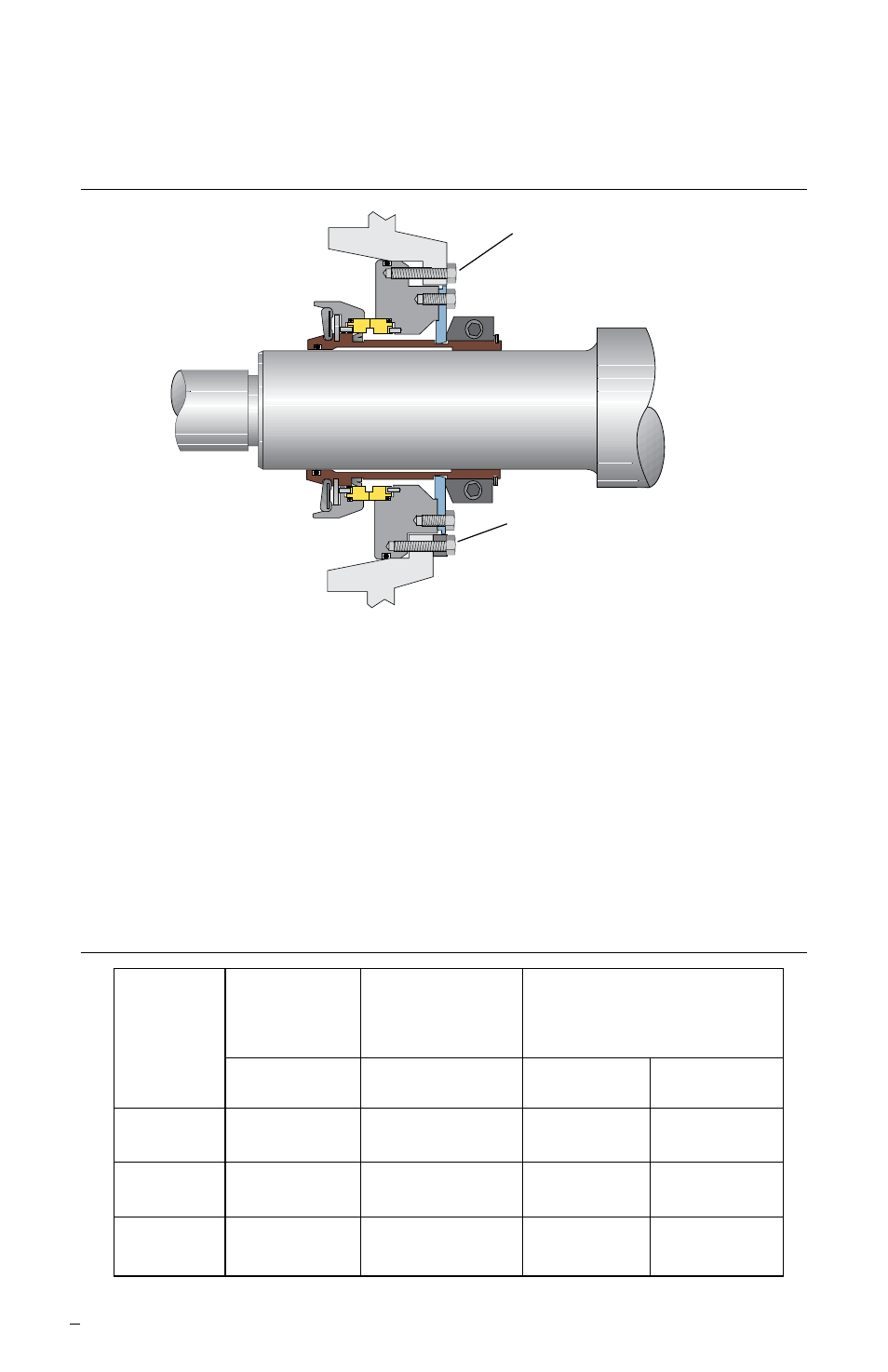
4.7 Slide retaining bolts through the rear face of the adapter plate and screw into
seal flange/gland. Evenly tighten retaining bolts to pull the seal into the adapter
fit. See Figure 7.
Draw Cartridge into Adapter Using Attachment Bolts Figure 7
With the Spacer Ring Removed
Evenly Tighten Flange/Gland Bolts
to Start the Seal into the Adapter
Insert the Spacer Ring and
Continue Even Tightening
of the Bolts until the
Flange/Gland is Properly Seated
4.8 Once the seal flange/gland has started into the adapter fit, remove the retaining
bolts and insert the spacer ring. Continue even tightening of the bolts until the
seal flange/gland is properly seated. See Figure 7. Some seals do not require
the use of the spacer rings; consult job drawing.
4.9 If seal is directly mounted on shaft and not on the pump sleeve install impeller
spacer hook sleeve (possibly modified), impeller, and suction cover.
4.10 Make any necessary impeller adjustments.
Important:
Loosen bearing assembly and drive belts only enough to make
adjustment. Fully tighten bearing assembly bolts after adjustment.
Torque Value Chart N-m (ft-lb) Figure 8
Split Clamp/ Group 4-5 Taper
Drive Cap
Ring Clamp/
Drive Collar
Screws
Drive Cap Screws
Set Screws
Fastener
Alloy
Alloy
Stainless Alloy
Size
Steel
Steel
Steel Steel
5/16”
33 - 35
27 - 30
14 - 16
18 - 20
(24 - 26)
(20 - 22)
(10 - 12)
(13 - 15 )
3/8”
54 - 61
33 - 37
20 - 23
30 - 34
(40 - 45)
(24 - 27)
(15 - 17)
(22 - 25)
1/2”
122 - 136
-
43 - 49
68 - 75
(90 - 100)
(32 - 36)
(50 - 55)