Install wet side cartridge figure 6 – Flowserve SLC Series Interseal User Manual
Page 5
5
4.3 For adapters provided with a centering jig, simply insert the centering jig into the
adapter and tighten adapter bolts, alternately adjusting the cover location until
the centering jig can be removed by hand.
Adapter Plate Mounting Surface Perpendicular to Shaft Figure 5
Adapter Mounting Surface to be
Perpendicular to Shaft within
0.25 mm (0.010 inch) FIM (TIR)
4.4 Dial indicate rear face of seal fit in the adapter plate. This fit must be perpendic-
ular to the shaft within 0.25 mm (0.010 inch) FIM (TIR). See Figure 5. If surface
is out of tolerance, correct by machining the faces of the locating fits. Be sure to
have all fits clean of dirt, rust and/or paint.
4.5 Apply a light coating of O-ring lubricant to the index finger and thumb and pull
seal sleeve and flange/gland O-ring elements through fingers to inspect for nicks
or cuts. Install O-rings in their proper groove locations. This process will prevent
an excessive amount of lubricant from being applied to O-ring elements (non-
petroleum based grease must be used with EPDM materials).
Caution:
Do not apply anti-seize or other lubrication to the equipment shaft or
shaft sleeve. Keep shaft or shaft sleeves clean and dry. The use of lubricants
will cause improper clamping pressure by the seal split clamp/drive collar.
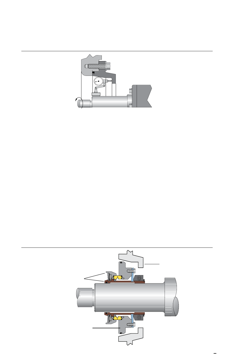
4.6 With the seal split clamp/drive collar pointing toward the bearing assembly,
slide the complete cartridge over the equipment shaft or shaft sleeve. Push seal
flange/gland back toward adapter plate. See Figure 6.
Important:
Do not hammer or push against rotary face housing or seal sleeve.
Do Not Hammer or Push
on Rotating Face Body
or Seal Sleeve
Seal Adapter
Push on Flange/Gland to Slide
the Seal Over the Shaft/Sleeve
Install Wet Side Cartridge Figure 6