Bolt cartridge to adapter plate face figure 13 – Flowserve SLC Series Interseal User Manual
Page 9
9
5.5 For adapters provided with a centering jig, simply insert the centering jig into the
adapter and tighten adapter bolts, alternately adjusting the cover location until
the centering jig can be removed by hand.
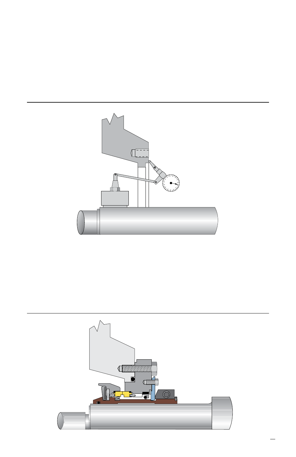
5.6 Dial indicate front face of seal fit on the adapter plate. This fit must be perpen-
dicular to the shaft within 0.25 mm (0.010 inch) FIM (TIR). See Figure 12. If
surface is out of tolerance, correct by machining the faces of the locating fits. Be
sure to have all fits clean of dirt, rust and/or paint.
Adapter Plate Mounting Surface Perpendicular to Shaft Figure 12
Adapter Mounting Surface to be
Perpendicular to Shaft within
0.25 mm (0.010 inch) FIM (TIR)
5.7 If seal is directly mounted on shaft and not on the equipment sleeve, install
impeller spacer hook sleeve (possibly modified) and impeller.
5.8 Slide seal flange/gland towards adapter to engage into the locating bore of the
adapter plate. Insert retaining bolts through flange/gland holes and screw into
front face of the adapter plate. Evenly tighten retaining bolts to pull the seal up to
the adapter fit. See Figure 13.
Bolt Cartridge to Adapter Plate Face Figure 13