Flowserve Circulator User Manual
Page 6
6
Section B:
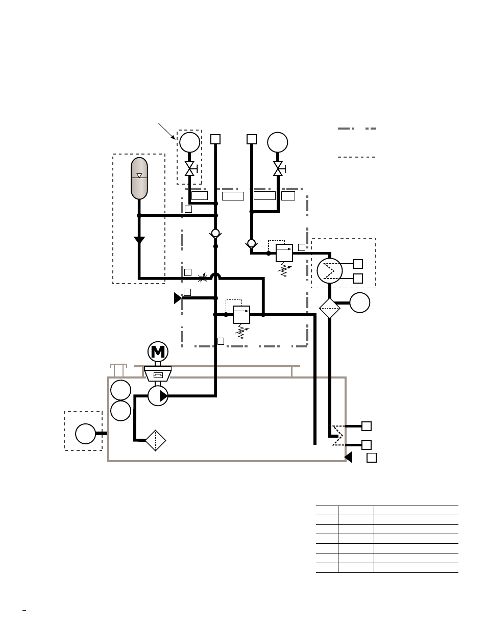
Piping and Instrumentation Diagram
Customer specific drawings can be found in Appendix 1.
Key
contained in
manifold block
contained in
optional kit
Optional
heat exchanger kit
(UKDPU9806)
RV-1 Factory set at 450 psig (3103 kPa)
PCV-1 Factory set at 200 psig (1379 kPa)
Reset PCV-1 as required
Optional
level switch kit
(UKDPU9805)
Optional
pressure switch kit
(UKDPU9802)
Optional
accumulator kit
(UKDPU9806)
PS
1
1
2
Pl
1
6
7
4
5
Pl
2
LS
1
LG
1
Tl
1
Test Port
3/4"
5/8"
1/2"
1/2"
3/4"
1/2"
1/2"
P
C
1/4"
1"
RV-1
B
5/8"
H
PCV-1
CV-2
CV-1
1-1/4"
A
PS-1
Supply
Return PI-1
Schedule of connections
connection
size
service
1
1/2" NPT
seal supply
2
1/2" NPT
seal return
3
3/4" NPT
drain (plugged)
4
1/2" NPT
cooling water supply (plugged)
5
1/2" NPT
cooling water return (plugged)
6
3/8" NPT
cooling water supply (option)
7
3/8" NPT
cooling water return (option)
3