Flowserve Circulator User Manual
Page 9
9
Option 3
The level switch kit includes:
• Level switch, 3/4” NPT
Kit Installation Instructions
1. Apply Teflon tape and/or Jomar pipe dope or equal
to level switch threads. Start no closer to the end of the
threads than the 2nd thread.
2. Clean any dirt or debris from the reservoir connection.
Remove 3/4” plug from reservoir coupling next to the
level gauge.
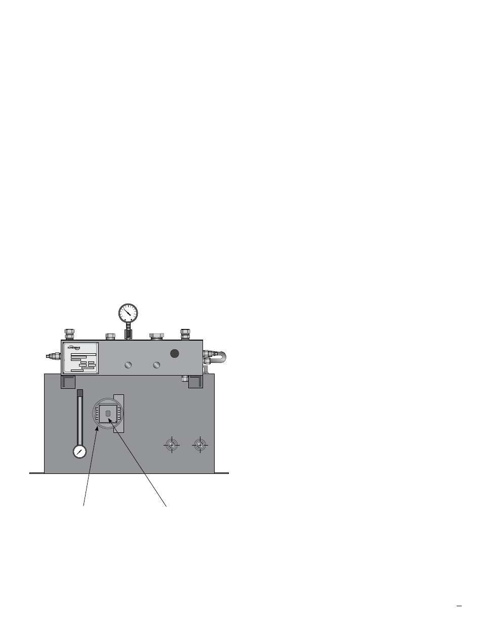
3. Thread in level switch. Tighten with flats on the shaft in
the vertical position. See figure 3.
4. Installation is complete.
5. It is the responsibility of the customer to wire the level
switch.
Option 4
The heat exchanger kit includes:
• Heat exchanger
• Heat exchanger mounting brackets
• U-bolts with nuts and mounting pad (quantity 2)
• Tube fittings (quantity 3)
• Tubing (quantity 3)
Kit Installation Instructions
1. Apply Teflon tape and/or Jomar pipe dope or equal to
the 4 tube fittings threads. Start no closer to the end of
the threads than the 2nd thread.
2. Remove tubing from the manifold block to the filter
and discard.
3. Attach heat exchanger mounting brackets with two (2)
1/2” 13 mounting bolts through the holes provided in
the top of the manifold block and finger tighten bolts.
See Figure 4.
4. Place a mounting pad on each mounting bracket
between the mounting holes.
5. Place the heat exchanger on the mounting pads. Shell
connection should be facing up with the cooling media
connections facing the drain side of the reservoir. See
Figures 4 and 5.
6. Install the U-bolts over the heat exchanger and
through the mounting pads and brackets and finger
tighten nuts.
7. Install and tighten tube fittings into the heat exchanger
shell connections. Do not over tighten.
8. While facing the unit from the block side, position the
heat exchanger approximately 4-1/2 inches (114 mm)
from the right side of the reservoir. See Figure 4.
9. Level the heat exchanger across the cooling media
ports. See figure 5.
10. Remove the fitting nuts and ferrules from the fittings
on the left side of the heat exchanger and the mani-
fold block. Assemble the short piece of tubing, 90°
union tube fitting and the short 90° bent tube into the
heat exchanger and the manifold block.
11. Verify tubing ends are the correct length. Cut to fit if
required. Proceed to the next step once tubing is the
correct length.
Figure 3
Seal Support System
Part No.
Part No.
PSI
to
to
Xxxxxxx
Xxxxxxx Xxxxx Xxxx Xx
Xxxxx xx xxxxxxxxx
Xxxxx xx xxxxxxxxxxx
Xxxxxx
Xxxx Xx.
Xxxx xxxxxx xxxx
xxxxxxxx xx xxxx
xxxxxx xxxxxxxxx
xxxxxx xxxxxxxxx
xxxxx
level switch
shaft position