4 dual seal piping and operational recommendations – Flowserve ISC Series User Manual
Page 11
CW
Rotation
F
D
F
Q
CCW
Rotation
11
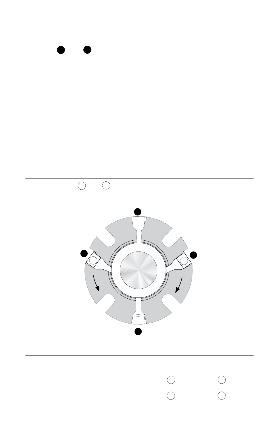
3.2 Use flush port that coincides with gland markings and direction of
equipment rotation. Plug extra NPT opposite of flush. See Figure 7.
3.3 Taps
Q
and
D
in the gland are quench and drain ports used for
fluid quenching, flush plan 62. If they are not used, they should be
plugged with pipe plugs.
3.4 Remove lock outs on pump and valves.
3.5 Do not start up the equipment dry to check motor rotation or for any
other reason. Open valves to flood pump with product fluid. Ensure
that the seal flush system is operating. Vent air from the casing of
the pump and the seal chamber before start-up.
3.6 Observe the start-up. If the seal runs hot or squeals, check the
seal flush system. Do not allow the equipment to run for any
extended time if the seal gets hot or squeals.
4 Dual Seal Piping and Operational Recommendations
4.1 Flush taps a and b in the gland are barrier fluid inlet and
outlet ports. Use Figure 8 to determine which ports to use as inlet
and outlet.
a
b
Shaft rotation from exposed end of gland
Figure 8
Inlet
Outlet
Clockwise (CW)
Port b
Port a
Counterclockwise (CCW)
Port a
Port b