Flowserve ISC Series User Manual
Page 9
9
2.5 Position the ISC with the gland tight against the seal chamber face.
If equipment conditions allow, position gland with the outlet port or
plugged flush port as close to the 12:00 o'clock position as possible.
See Sections 3 and 4 for further piping considerations. Otherwise turn
the gland so that the vent tap is as close to the 12:00 o’clock position
as possible and so that the flush piping will clear the bearing frame.
Caution:
Setting devices should not be removed or loosened before tighten-
ing the gland bolts and tightening the set screws to the shaft.
Tighten the gland nuts evenly in a diagonal sequence. Do not over
tighten the gland nuts, as this can warp seal parts and cause leakage.
Confirm adequate thread engagement before final torque setting.
Figure 6
Figure 5
The suggested ISC minimum torque
values are as follows for seals with
these shaft sizes (in inches):
15 ft-lbs (20 N-m) 20 ft-lbs (27 N-m)
1.000
2.125
to
to
2.000
2.750
2.6 Assemble the pump. Avoid pipe
strain. Align coupling properly.
2.7 With the impeller, shaft, coupling,
and bearings in their final operating
positions, tighten the drive collar
set screws. See Figure 5.
Suggested minimum torque values for set screws are as follows:
Shaft Sizes 25 - 60 mm (1.000 - 2.500 inches)
1
4
" 4.5 N-m (40 inch-lbs)
Shaft Sizes 67 - 70 mm (2.625 - 2.750 inches)
3
8
" 13.6 N-m (120 inch-lbs)
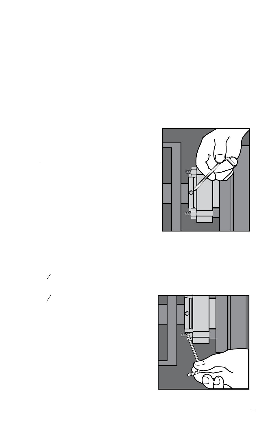
2.8 Caution: Remove the setting
devices from the drive collar.
See Figure 6. Save these and the
fasteners for future use when the
pump impeller is reset or when the
seal is removed for repairs.
2.9 Turn the shaft by hand to ensure
unobstructed operation.
2.10 See Operational
Recommendations before start-up.