Seal chamber requirements figure 1, 2 isc2 seal installation – Flowserve ISC2 Series User Manual
Page 3
3
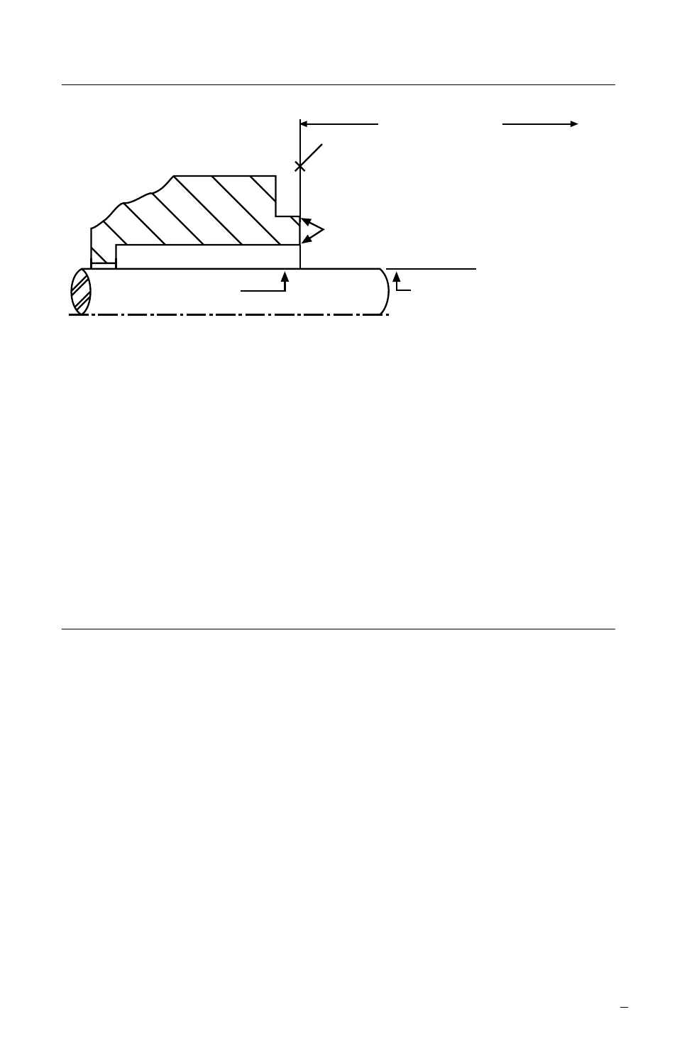
Seal Chamber Requirements
Figure 1
1.8 Handle the ISC2 seal with care; it is manufactured to precise tolerances.
The seal faces are of special importance and should be kept perfectly
clean at all times.
1.9 Tools needed for installation: An open-end wrench and torque wrench
sized for the gland bolt nuts; a torque wrench for the set screws. All other
tools are provided.
2 ISC2 Seal Installation
Note: No seal setting measurements
are needed to install the seal.
Instructions are for end-suction back pull-out pumps. Modification of these
procedures may be required for other style pumps. Consult Flowserve for
installation support.
2.1 Lubricate the shaft or pump sleeve lightly with silicone lubricant unless
otherwise specified.
2.2 Tighten the setting device cap screws to ensure they are tight before
installation.
To first obstruction
Face of seal housing to be square to the
axis of the shaft to within 0.0005 mm/mm
(0.0005 inch/inch) of seal chamber bore TIR
and have a 1.6
μ
m (63
μ
inch) R finish or better
a
Gland pilot can be at either of these
register locations, concentric to within
0.125 mm (0.005 inch) of shaft or
sleeve OD TIR
Seal housing bore to have 3.2 μm
(125 μinch) R finish or better
Sleeve or shaft finish to be
0.8 μm (32 μinch) R or better
a
a
• Bearings must be in good condition
• Maximum lateral or axial movement of shaft (end play) = 0.25 mm (0.010 inch) TIR
• Maximum shaft runout at face of seal housing = 0.05 mm (0.002 inch) TIR
• Maximum dynamic shaft deflection at seal housing = 0.05 mm (0.002 inch) TIR
Shaft or sleeve OD
+0.000 mm (+0.000 inch)
-0.050 mm (-0.002 inch)
+0.000 mm (+0.000 inch) API 610/682
-0.025 mm (-0.001 inch) DIN/ISO
ANSI