Flowserve ISC2 Series User Manual
Page 6
Plan 02: dead-ended seal chamber with no flush
(single seals, always plug Flush port)
Plan 03: circulation created by the design of the seal chamber
(single seals, always plug Flush port)
Plan 11: default inner seal flush from pump discharge on horizontal pumps
(single seals)
Plan 13: default inner seal flush and vent from pump suction on vertical
pumps (single seals)
Plan 21: inner seal flush from pump discharge through a cooler for use
with hot products (single seals)
Plan 23: inner seal flush from internal pumping device through cooler
(ISC2-XP and ISC2-XB designs)
Plan 32: inner seal clean external flush for use with abrasive products or
products that are incompatible with the seal (single seals)
Plan 52: dual seal circulation through a low pressure reservoir (dual seals)
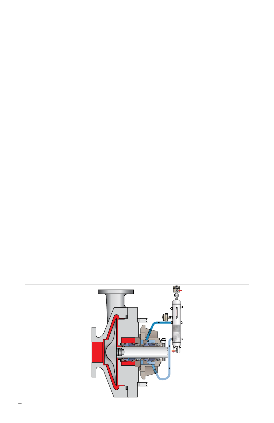
Plan 53: dual seal circulation through a pressurized reservoir (53A), finned
tube array (53B) or piston accumulator (53C) (dual seals)
Plan 62: external quench on atmospheric side of seal (single seals)
3.2 For dual seals, LBI (Liquid Barrier Inlet) and LBO (Liquid Barrier Outlet)
are marked on the gland
. ISC2 seals are unidirectional and piping the
correct inlet and outlet is important to proper circulation. The liquid barrier
inlet should draw from the bottom of the support system while the liquid
barrier outlet feeds the top of the system.
3.3 For dual pressurized seal (Plan 53, double seal) operation, supply a
clean, compatible barrier fluid at a pressure at least 1.7 bar (25 psi) above
the seal chamber pressure. See Figure 6. The pressure of the barrier fluid
must not exceed the recommended maximum pressure.
Dual pressurized (Plan 53A) ISC2 with Supply Tank
Figure 6
6