Flowserve ISC2 Series User Manual
Page 4
4
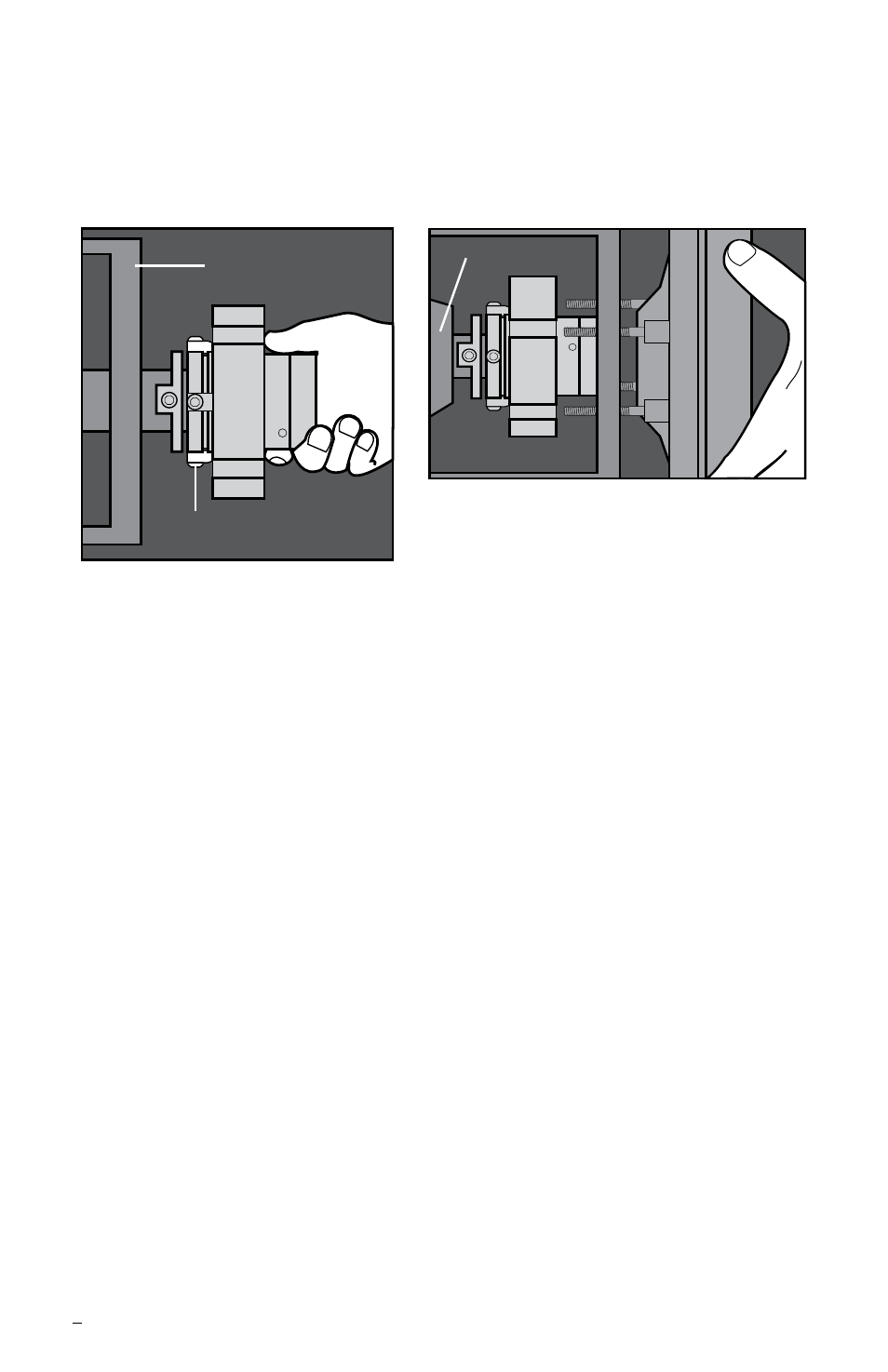
Figure 2
Setting Device
Bearing Frame
Seal
Chamber
Figure 3
Bearing Housing
2.3 Slide the ISC2 seal cartridge onto the shaft or pump sleeve with the
setting devices toward the bearing housing. See Figure 2.
2.4 Install the seal chamber and bolt it in place on the bearing frame.
See Figure 3.
2.5 Position the ISC2 seal with the gland tight against the seal chamber.
2.6 Orient the ISC2 seal with the ports aiming as shown on the seal
assembly drawing. See Section 3 for Piping Recommendations.
2.7 Tighten the gland nuts evenly in a diagonal sequence. Do not over-
tighten the gland nuts, as this can warp seal parts and cause leakage.
Confirm adequate thread engagement before final torque setting.
Recommended ISC2 seal minimum gland nut torque by size range:
Seal
mm
25 - 50
54 - 70 75 - 102 108 - 152 159 - 203
Size
(inch) (1.000 - 2.000) (2.125 - 2.750) (2.875 - 4.000) (4.250 - 6.000) (6.250 - 8.000)
Torque
20 N-m
27 N-m
40 N-m
47 N-m
54 N-m
(15 ft-lbs)
(20 ft-lbs)
(30 ft-lbs)
(35 ft-lbs)
(40 ft-lbs)
Note: Some equipment with small bore seal chambers provide limited access
to the gland bolting and setting device cap screws. In some situations, the gland
fasteners interfere with the setting devices and window access may require
deviation from the standard fastening sequence. For example, the collar/sleeve
assembly may need to be rotated slightly from its factory-set position by loosening
the setting device cap screws, rotating the collar/sleeve assembly, then tightening
the screws. When nonstandard processes are followed, be careful to maintain
the integrity of the seal cartridge at all times.