Flowserve ISC2 Series User Manual
Page 5
5
Figure 4
2.8 Assemble the equipment per manufacturer specifications. Avoid pipe
strain. Align the coupling per manufacturer specifications.
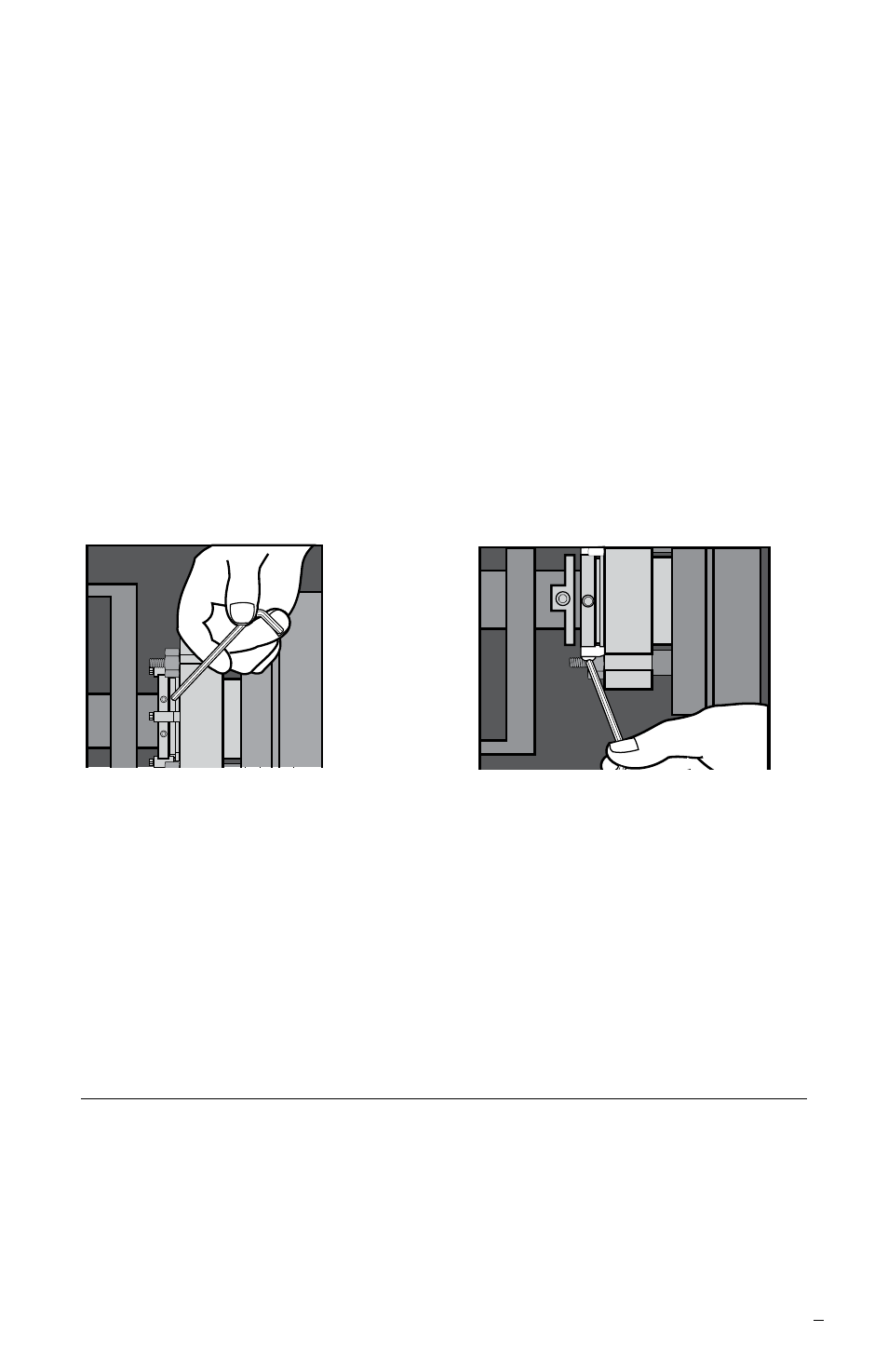
2.9 With the impeller, shaft, coupling and bearings in their final operating
position, tighten the drive collar set screws. See Figure 4. Note: in designs
that have two smaller screws, these are quarter dog screws that hold the
collar to the sleeve and should not be tightened. A hex key was provided
for the set screws, not for the quarter dog screws.
Recommended ISC2 seal minimum set screw torque by size range:
Seal
mm
25 - 60 67 - 70
75 - 203
75 - 203
Size
(inch) (1.000 - 2.500) (2.625 - 2.750) (2.875 - 8.000) (2.875 - 8.000)
Gland Size
All
All
Standard Bore Enlarged Bore
Torque
4.5 N-m
13.5 N-m
16.9 N-m
27.1 N-m
(40 in-lbs)
(120 in-lbs)
(150 in-lbs)
(240 in-lbs)
2.10 Remove the setting devices from the drive collar by loosening the cap
screws. See Figure 5. Save the setting devices and fasteners for future use
when the pump impeller is reset or when the seal is removed for repairs.
2.11 Turn the shaft by hand to ensure unobstructed rotation.
2.12 See Operational Recommendations before start-up.
3
Piping Recommendations
3.1 Install and maintain an adequate piping plan. The ISC2 seal requires a
clean, cool environment for maximum seal life. Typical piping plans are
listed below. Contact Flowserve for additional piping plan information
or technical support. Important: All red plastic caps/thread guards are
for shipping protection only and should be replaced with either a piping
connection or a metal plug in the same metallurgy as the gland.
Figure 5