Connections – Flowserve PMV P4 User Manual
Page 10
10
Air connections are tapped for 1/4" G or NPT male connectors and are clearly marked.
Gauge ports are for 1/8" G or NPT.
We recommend use of Loctite® 577 or similar user preferred for sealing.
Electrical connection on I/P unit accepts 1/2" NPT or PG 13,5 (M20) cable gland.
Port I
Input instrument pneumatic signal 20-100kPa (3-15 psi)
Port S
Supply air, maximum 1 MPa (150 psi) Minimum 0,15 MPa
(21 psi) for EP5
Port C1, C2 Actuator connections (0,2-1 MPa). C2 opening port.
For single acting operation plug port C1 for increasing signal to open valve. Plug C2 for
decreasing (reverse) signal to open valve.
OUT
Exhaust air port. Do not block! Exhaust filter optional.
Port Ip
Gauge port for pneumatic input signal.
Port I
E
Input electric signal (4-20 mA) (On the I/P unit.)
Port P
Gauge port for I/P unit output pressure ( On the I/P unit)
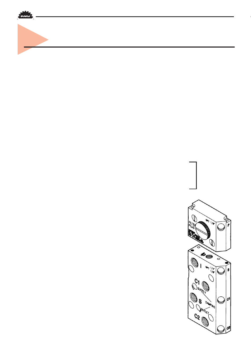
5. Connections
P5/EP5 only
Ports Ip, P, S, C1 and C2 are sealed with plugs. To install gauges,
unscrew plugs and replace with gauges.
Port OUT is for venting the unit. All air from the positioner, actuator
and I/P unit is vented to atmosphere through this port. Do not block
this port. A high flow silencer or an exhaust pipe can be connected to
this port to prevent foreign objects from entering and blocking the
units exhaust. Connector in exhaust port must not have less than 9
mm (3/8“) orfice.
When using gases other than air for supply — Please contact PMV.
On EP5 (P5 with I/P unit installed) I/P unit is supplied with air from
port S. Port’I is automaticly sealed off and protected. No connection
shall be made to this port. See pages 13 and 14 for more information.