Disassembly and reassembly – Flowserve Valtek VL Spring Cylinder Linear Actuators User Manual
Page 3
Valtek Spring Cylinder Linear Actuators FCD VLENIM002-00-AQ 10/14
3
flowserve.com
8. Spray soap solution around the cylinder retaining ring, the adjusting
screw and the lower actuator stem bushing to check for air leaks
through the O-rings and gasket.
9. Clean any dirt or foreign material from the actuator stem.
10. If an air filter is supplied, check and replace cartridge as necessary.
DISASSEMBLY AND REASSEMBLY
Disassembling the Actuator
Refer to Figures 1 through 5 to disassemble the cylinder actuator.
1. Shut off air supply. If the actuator is installed on a Valtek valve,
remove the actuator per Installation Operation and Maintenance
Instructions 1. If installed on other valves, remove the yoke to
bonnet connections, loosen stem clamp bolt and turn actuator
off of plug stem threads.
a
WARNING: To avoid serious injury, depressurize the line to
atmospheric pressure and drain all fluids before working on
the actuator.
2. Disconnect all tubing. Remove stem clamp and stem bellows from
the actuator stem.
3. Relieve spring compression completely by removing the adjusting
screw. Remove adjusting screw gasket from adjusting screw.
a
CAUTION: Do not use a screwdriver or bar to turn the adjusting
screw; instead, use a wrench on the flats of the screw.
a
WARNING: To avoid serious personal injury, relieve the spring
compression before further disassembly. The cylinder could
possibly fly off the yoke when removing the cylinder retaining
ring.
4. Remove the cylinder retaining ring from the groove at the base of
the cylinder by using two screw¬drivers. Insert one screwdriver
in slot found in the ring and pry the ring from the groove. Use the
other screwdriver to help work the ring out of the cylinder groove.
5. Pull the cylinder off the yoke and piston; some O-ring resistance
may be felt.
a
WARNING: To avoid serious personal injury, do not use air
pressure to remove the cylinder. The cylinder could possibly fly
off the yoke.
6. For heavy-duty spring designs using a spring cap (see Figure 4),
remove the spring cap and cap O-ring from the cylinder.
7. For air-to-extend configurations, slowly loosen and remove the
actuator stem locknut. Be certain the piston follows the stem
locknut up the actuator stem and does not bind on the actuator
stem. Remove the actuator stem
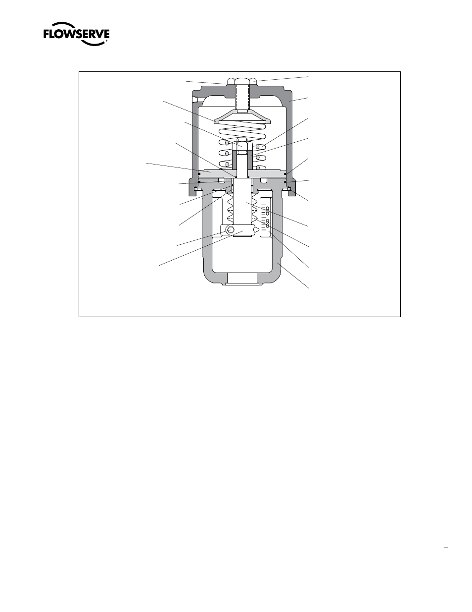
NOTE: Item numbers correspond directly to actuator’s bill of material. Refer to it for specific part numbers
Figure 1: Air-to-retract Cylinder Actuator
O
S
Adjusting Screw Gasket
(Item No. 248 )
Spring Button
(Item No. 227 )
Actuator Stem Locknut
(Item No. 348 )
Piston Stem O-ring
(Item No. 272 )
Piston
(Item No. 225 )
Upper Stem Bushing
(Item No. 253 )
Actuator Stem O-ring
(Item No. 275 )
Lower Stem Bushing
(Item No. 254 )
Stem Clamp Bolting
(Item No. 240/345 )
Stem Clamp
(Item No. 249 )
Adjusting Screw
(Item No. 210)
Cylinder
(Item No. 202)
Spring
(Item No. 229)
Stem Spacer
(Item No. 223)
Piston O-ring
(Item No. 271)
Yoke O-ring
(Item No. 274)
Cylinder Retaining
Ring
(Item No. 256)
Actuator Stem
(Item No. 211)
Stem Bellows
(Item No. 247)
Stroke Plate
(Item No. 213)
Yoke
(Item No. 201)