Reversing the air-action – Flowserve Valtek VL Spring Cylinder Linear Actuators User Manual
Page 5
Valtek Spring Cylinder Linear Actuators FCD VLENIM002-00-AQ 10/14
5
flowserve.com
9. Re-insert the cylinder retaining ring by until it snaps in place. Use
a hammer and drift punch to lightly tap the retaining ring in the
groove.
a
WARNING: To avoid personal injury, the cylinder retaining ring
must be solidly in place. The cylinder could possibly fly off
when pressurized. Be careful not to pinch or cut fingers on the
square edges of the retaining ring during installation.
10. Reinstall the adjusting screw using a new adjusting screw gasket.
NOTE: Be certain the hole in the spring button is directly
centered under the adjusting screw hole in the cylinder on
air-to-retract configurations.
11. Tighten the adjusting screw enough to provide an air seal with the
gasket. Do not over tighten.
12. Reinstall the stem bellows and stem clamp.
NOTE: To ensure maximum clamping strength when installing
the stem clamp, make sure the stem clamp bolting is perpen-
dicular to one of the slots machined into the actuator stem. 13.
Apply air over the piston. Tighten the stem clamp bolting with
the stem clamp adjusted to point at the closed position of the
stroke indicator plate.
NOTE: If the actuator is installed on a Flowserve valve, refer to
Installation, Operation, Maintenance Instructions 1 for correct
plug stem thread engagement.
14. Reconnect tubing, supply and signal lines.
Reversing the Air-action
To change the air action from air-to-retract to air-to extend, or vice
versa, refer to Figures 1, 2 or 5:
NOTE: Heavy-duty spring actuators are not reversible.
1. Disassemble the actuator according to the “Disassembling the
Actuator” section.
2. For air-to-retract action, reassemble the actuator with stem spacer
and spring button over the piston.
3. For air-to-extend action, reassemble with spring and stem spacer
below the piston and with the spring button stored above the
piston.
4. Reassemble the actuator according to the “Reassembling the
Actuator” section.
5. The positioner must also be reversed. See the appropriate
positioner maintenance instructions.
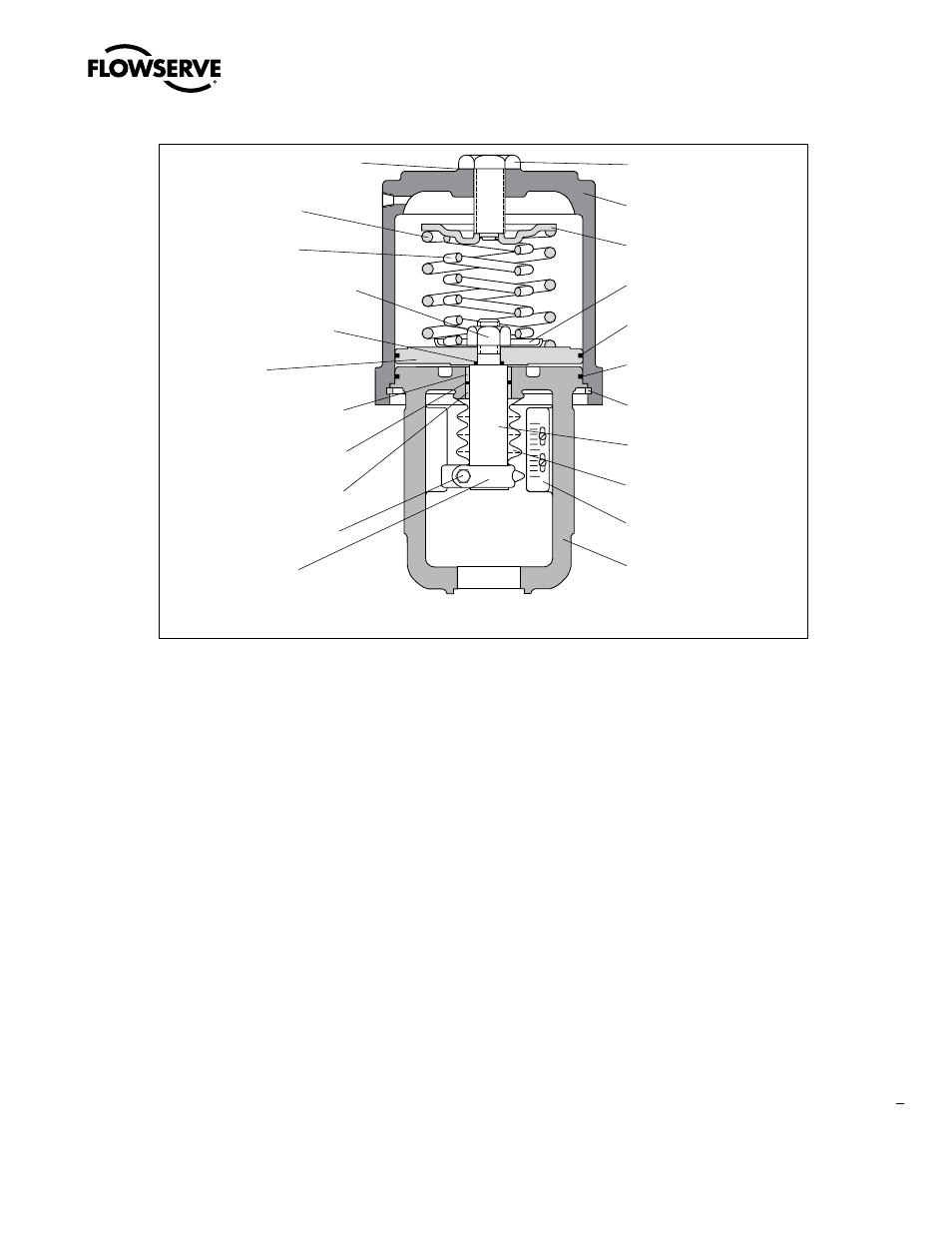
NOTE: Item numbers correspond directly to actuator’s bill of material. Refer to it for specific part numbers.
Figure 3: Dual-spring Cylinder Actuator
O
S
Adjusting Screw Gasket
(Item No. 248 )
Outer Spring
(Item No. 229 )
Inner Spring
(Item No. 230)
Actuator Stem Locknut
(Item No. 348 )
Piston Stem O-ring
(Item No. 272 )
Piston
(Item No. 225 )
Upper Stem Bushing
(Item No. 253 )
Actuator Stem O-ring
(Item No. 275 )
Lower Stem Bushing
(Item No. 254 )
Stem Clamp Bolting
(Item No. 240/345 )
Stem Clamp
(Item No. 249 )
Adjusting Screw
(Item No. 210)
Cylinder
(Item No. 202)
Spring Button
(Item No. 227)
Spring Guide
(Item No. 326)
Piston O-ring
(Item No. 271)
Yoke O-ring
(Item No. 274)
Cylinder Retaining Ring
(Item No. 256)
Actuator Stem
(Item No. 211)
Stem Bellows
(Item No. 247)
Stroke Plate
(Item No. 213)
Yoke
(Item No. 201)