Reassembling the actuator – Flowserve Valtek VL Spring Cylinder Linear Actuators User Manual
Page 4
Valtek Spring Cylinder Linear Actuators FCD VLENIM002-00-AQ 10/14
4
NOTE: The dual, heavy-duty spring configuration (Figure 3) has
two springs, one inside the other. Remove both springs during
this step.
8. Remove the piston O-ring, piston stem O-ring and yoke O-ring.
9. Remove the actuator stem O-ring.
NOTE: The upper and lower stem bushings are pressed into
the yoke Removal of the bushings to replace the actuator stem
O-ring is unnecessary.
10. Use appropriately sized press to push worn or damaged bushings
out of yoke.
Reassembling the Actuator
To reassemble the cylinder actuator, refer to Figures 1 through 5:
1. All O-rings should be replaced. New O-rings should be lubricated
with a silicone lubricant (Dow Corning 55M or equivalent).
Silicone O-rings must be lubricated with Magnalube-G lubricant
or equivalent. Do not use silicone lubricant on silicone O-rings.
2. Thoroughly clean all internal parts before beginning assembly.
Lubricate cylinder wall with silicone lubricant.
3. Lubricate the outside of the replacement bushings if the stem
bushings have been removed. Press a new lower stem bushing
into the actuator stem bore in the yoke until it bottoms out. Press
the upper stem bushing into the bore until it is flush with the top
of the yoke (refer to Figures 1 or 2).
4. Replace the actuator stem O-ring and yoke O-ring.
5. Reassemble the piston, piston stem O-ring and stem spacer on
the actuator stem according to the proper air-action (refer to
either Figure 1 or 2). Replace the piston O-ring. Air-to-extend
configurations require the spring button to be stored under
actuator stem locknut. Tighten the locknut firmly.
NOTE:
When reassembling heavy-duty, spring design actua-
tors, the spring guide must be first inserted under the actuator
stem locknut (see Figures 3 and 4).
6. For air-to-extend configurations, place the spring under the piston
and insert the actuator stem through the yoke, being careful not to
pinch the actuator stem O-ring or gall the stem and stem bushings.
For air-to-retract configurations, insert the actuator stem through
the yoke and place the spring(s) and spring button above the
piston.
7. Replace the cap O-ring and install the spring cap in the cylinder
when using heavy-duty spring designs using spring caps
(see Figure 4).
8. Install the cylinder, making sure the yoke is pushed deeply enough
into the cylinder to allow the cylinder retaining ring to be installed.
Care should be taken not to scar or cut the piston and yoke
O-rings.
O
S
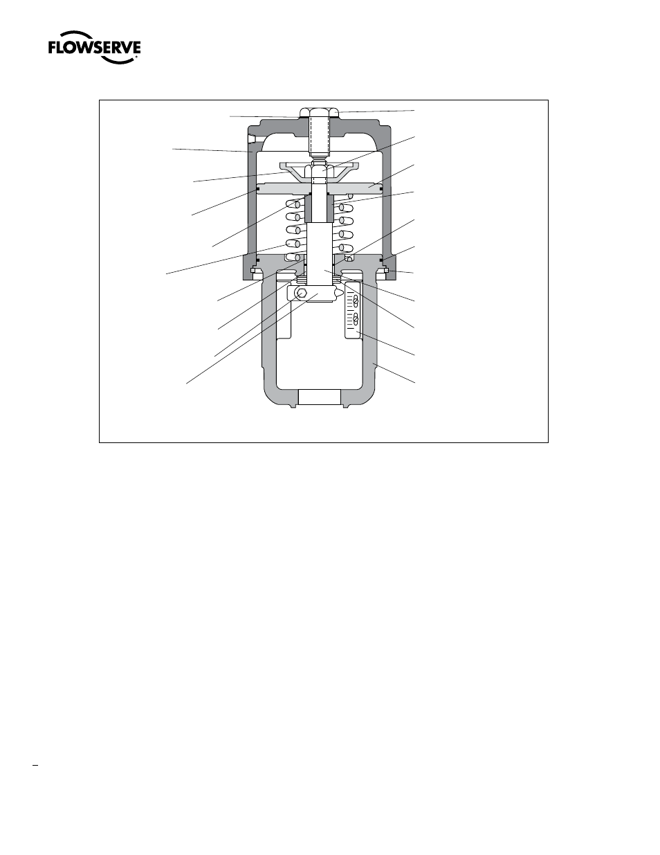
Adjusting Screw Gasket
(Item No. 248)
Cylinder
(Item No. 202)
Spring Button
(Item No. 227)
Piston O-ring
(Item No. 271)
Piston Stem O-ring
(Item No. 272)
Spring
(Item No. 229)
Upper Stem Bushing
(Item No. 253)
Lower Stem Bushing
(Item No. 254)
Stem Clamp Bolting
(Item No. 240/345)
Stem Clamp
(Item No. 249)
Adjusting Screw
(Item No. 210)
Actuator Stem Locknut
(Item No. 348)
Piston
(Item No. 225)
Stem Spacer
(Item No. 228)
Actuator Stem O-ring
(Item No. 275)
Yoke O-ring
(Item No. 274)
Cylinder Retaining Ring
(Item No. 256)
Actuator Stem
(Item No. 211)
Stem Bellows
(Item No. 247)
Stroke Plate
(Item No. 213)
Yoke
(Item No. 201)
NOTE: item numbers correspond directly to actuator’s bill of material. Refer to it for specific part numbers.
Figure 2: Air-to-extend Cylinder Actuator