Flowserve G4 Sleeveline Plug Valves User Manual
Page 10
10
G4, G4ZHF AND G4R USER INSTRUCTIONS ENGLISH 5-14
SECTION V
B. VALVE ASSEMBLY – 1"–8" G4, G4R
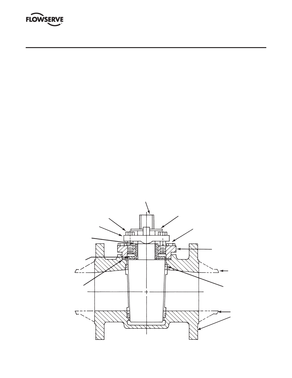
FIGURE V B-7
ASSEMBLED G4 OR G4R VALVE
ADJUSTER FASTENERS (12A)
PLUG (2)
ADJUSTER (12)
GROUND SPRING (17)
THRUST COLLAR (11)
DIAPHRAGM (6)
STOP COLLAR & RETAINER (19A)
TOP CAP FASTENERS (3A)
TOP CAP (3)
BODY (1)
SLEEVE (5)
BODY,
G4R OR
G4
8. Place the grounding spring (Part 17) over the plug stem.
9. Place the top cap and adjuster over the plug stem. Place
this subassembly into the valve body using an arbor
press to hold the top of the plug flush with the counter-
bore. (The bottom of the plug ports should be lined up
with the bottom of the body ports.) Push down on the
press until the top cap gasket pad seats firmly against
the body counterbore. Apply thread locking compound
to the threads of the top cap fasteners. Tighten the top
cap fasteners (Part 3A) to a value consistent with industry
standards for size and alloy type. Ref. Torque Table #1a
& #1b on page 11.
10. Remove the valve from the arbor press, loosen the
adjuster fasteners, and operate the plug several times. It
will turn hard at first but will then loosen and turn freely.
11. Tighten the adjuster fasteners (Part 12A) until a
reasonable turning torque (Ref. Table #2 on page 11)
is obtained. The 8" and larger valves are placed in an
oven at 200°F for a minimum of six hours prior to final
adjustment with the plug in the open position. After
removal from the oven and valve has cooled, loosen the
adjuster fasteners. Turn the plug several times. Retighten
the adjuster fasteners until a reasonable plug turning
torque is obtained. The height of the plug port should be
positioned approximately
1
/
16
" above to flush with the
body port.
12. Place the stop collar (Part 19A) and retainer on the plug
stem. The stop collar should point in the direction of flow.
13. The valve is now ready for test and use.
14. LEAK TESTING: Any time a valve has been modified in
any manner, including fastener changes, it should be
retested. Normal testing, using gas, should be at 150 PSI
for Class 150 and 300 PSI for Class 300 valves from
1
/
2
"
through 6". It should be noted, how ever, that this test
does not meet the requirements of ANSI, API or MSS.
For test procedures complying with these speci fications,
refer to the appropriate published speci fication.