G4, g4r – Flowserve G4 Sleeveline Plug Valves User Manual
Page 8
8
G4, G4ZHF AND G4R USER INSTRUCTIONS ENGLISH 5-14
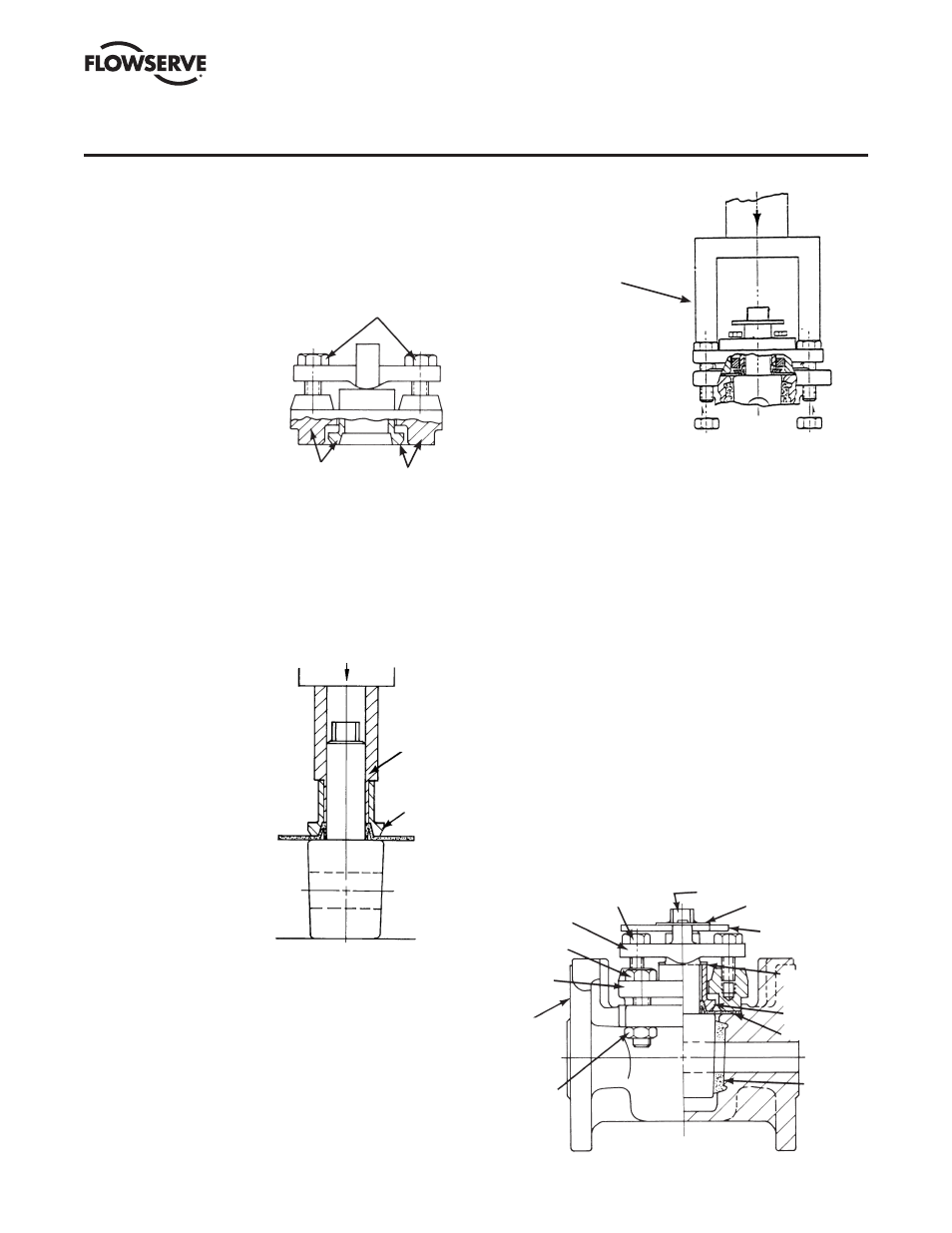
6. Remove thrust collar
from top cap and
as sem ble over the plug
stem (Figure V A-6).
With the thrust collar
guide, part #BY77545A,
centering the thrust
collar, force down (with
arbor press) thrust
collar guide to seat the
dia phragm stem seal in
the thrust collar.
7. Place grounding spring
over plug stem, sliding
it down to the thrust
collar.
8. Apply a thin, even film
of silicone or customer-approved lubricant to the entire
surface of the 2° plug taper.
9. Take plug (preassembled with diaphragm, thrust collar
and grounding spring) and place it into body. Using a
soft head mallet, tap
top of plug slightly to
seat plug into sleeve
taper. The plug at this
time will be set ting up
above the body
counter bore ap prox-
imately
1
/
4
". The plug
ports should be lined
up in an open posi tion.
10. Place the top cap
assembly over plug
and slide it down until
it rests on the thrust
collar.
11. Assemble four
fasteners thru top
cap and body. With
“U” shaped push
plate, part #BY80020A,
resting on the top cap (Figure V A-7), force the top
cap down (with arbor press or pneumatic clamping
arrangement) to seat the top cap against the valve body
counter bore. While holding the cap in this position,
assemble nuts on underside of body flange to a finger-
tight position against the flange. Coat the fastener
threads with Loctite
®
242.
12. Tighten the four top cap fasteners to 7 ft-lb using a
torque wrench. Reference Torque Table #1a & 1b on
page 11.
NOTE: All fastening
torques are for corro sion-
free fasteners and nuts.
Precautions must be
taken not to exceed
recommended fastening
torques.
13. Loosen the adjuster fasteners to approximately
3
/
16
"
above adjuster. Then rotate the valve plug back and forth
three times, making it rise upward.
14. Retighten adjuster fasteners to a torque of 10 to 12 in-lb.
The height of the plug port should now be positioned
approximately
1
/
16
" above to flush with the body port.
15. Rotate plug back and forth a couple of times to make
sure the stops and ports line up properly. The final
assembled valve should look similar to Figure V A-8.
16. LEAK TESTING: Any time a valve has been modified in
any manner, including fastener changes, it should be
retested. Normal testing, using gas, should be at 150 PSI
for Class 150 and 300 PSI for Class 300 valves from
1
/
2
"
through 6". It should be noted, how ever, that this test
does not meet the requirements of ANSI, API or MSS.
For test procedures complying with these speci fications,
refer to the appropriate published speci fication.
SECTION V
A. VALVE ASSEMBLY –
1
/
2
" &
3
/
4
" G4, G4R
FIGURE V A-8
ASSEMBLED VALVE
ADJUSTER FASTENER
ADJUSTER
TOP CAP
FASTENER
TOP CAP
BODY
TOP CAP
NUT
PLUG STOP COLLAR
RETAINER
STOP COLLAR
GROUNDING
SPRING
THRUST
COLLAR
DIAPHRAGM
SLEEVE
FIGURE V A-7
ASSEMBLE TOP CAP ASSEMBLY
OVER PLUG AND PUSH INTO BODY
TOP CAP ASSEMBLY
PUSH PLATE
FIGURE V A-5
PRESET ADJUSTER, THRUST
COLLAR AND TOP CAP
SET ADJUSTER CAP SCREWS
TO MAKE ADJUSTER
PARALLEL TO TOP CAP
BOTTOM OF TOP CAP AND
THRUST COLLAR FLANGE
TO BE FLUSH
THRUST
COLLAR
GUIDE
THRUST
COLLAR
FIGURE V A-6
SEAT THRUST
COLLAR ON DIAPHRAGM