Wiring, Fig. 5 – Flowserve ORGS 11-2 User Manual
Page 12
12
Use multi-core flexible control cable with min. conductor size 1.5 mm² for wiring.
1. Undo screws and remove the housing cover , Fig. 3
2. Unscrew union nuts of cable entries .
3. Slacken plug with 17 mm open-end spanner but do not remove it. Fig. 4
The electrode terminal can be turned through +/– 180°.
4. Turn electrode terminal into desired direction (+/– 180°).
5. Tighten plug slightly.
6. Remove terminal strip from board.
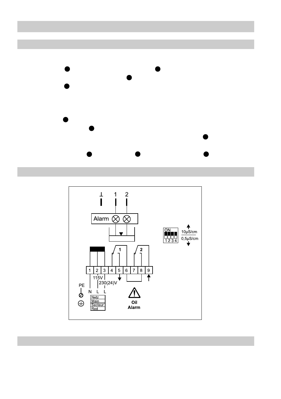
7. Connect terminal strip according to wiring diagram, establish PE connection.
8. Plug in terminal strip.
9. Mount housing cover , fasten screws and install cable entry .
Wiring
Tools
Wiring diagram
■
Screwdriver for cross head screws, size 1
■
Screwdriver for slotted screws, size 2.5, completely insulated according to
VDE 0680
■
Open-end spanner 17 mm A. F. to DIN 894
Fig. 5
N
I
H
J
K
K
H
H
I
J
Position of contacts: de-energized, alarm, LEDs 1 and 2 not illuminated
Measuring electrode ORGS 11-1