Worcester controls – Flowserve Factory Mutual Approved Oil or Gas Safety Shutoff Valve User Manual
Page 8
8
Factory Mutual Approved Oil or Gas Safety Shutoff Valves
WCAIM2054
D. 39S Actuator
NOTE: For identification of all numbered parts discussed below,
consult exploded view of actuator.
INCLUDED IN ALL 39 ACTUATOR REPAIR KITS IS A REBUILD/
ACCESSORY ADDITION LABEL, WHICH IS TO BE MARKED WITH A
PERMANENT MARKER AND THEN APPLIED TO THE ACTUATOR
AFTER ACTUATOR HAS BEEN REPAIRED.
1. Actuator
Disassembly
a. Disconnect the air supply and electrical service to the
actuator.
b. Remove the actuator and its mounting bracket from the
valve. If the actuator uses a positioner, loosen the set
screws in the coupling between the valve and actuator.
CAUTION: Ball valves can trap pressurized media in the
cavity. Isolate the piping system in which the
actuator/valve assembly is mounted and relieve any
pressure on the valve. Note orientation of actuator to
valve. It is important that the actuator be remounted in
the same position to assure fail-safe operation.
c. Remove the actuator bracket from the actuator to begin
repair. Remove positioner (if used) by loosening
positioner coupling set screws, removing positioner
bracket screws and hose connections.
d. It is not necessary to remove solenoid control block (7) to
rebuild actuator. However, if it becomes necessary to
remove the block, begin by removing the solenoid block
bolts (8E). Use care to retain the solenoid block gasket (9).
e. Each end cap (5A, 5B) is aligned onto the body (1) over a
“foolproof pin”. This ensures that the end caps can only
be assembled to their respective end of the actuator.
Remove all four metric screws (5C) from and remove
both end caps. For Rev. R1 and R3 through R6 actuators,
remove the two bearings (6A) and O-rings (15A and 15B)
from each end cap. Note that for Rev. R2 models with
top-hat-style bearings (6C), the bearings and particularly
the retaining washers (16) in each end cap should not be
disturbed during O-ring seal replacement, as they are not
included in the rebuilding kit.
CAUTION: The actuator is a spring-return model. First
remove two end cap screws diagonally opposite each
other, then lubricate the threads and under the head.
Replace the screws and repeat the procedure for the
other two screws. Do this for each end cap, as this will
aid reassembly. Now uniformly loosen all four end cap
screws on each end cap two to three turns at a time, in
sequence, to relieve pre-load of the springs. End cap
screws are long enough to allow springs to relieve
before disengaging. Note position of springs, gently
pry off each end cap and use caution when removing
end caps.
f. The two piston guide rod assemblies (4) can now be
removed from each end of the body and disassembled by
removing the piston set screws (12). Do not interchange
piston guide rods and their respective piston. For sizes
10–20 Rev. R6, each guide rod and piston may be press
fitted together (do not use set screws) and cannot be
disassembled. (To assist reassembly, mark the body with
a line on the side from which the guide rod using the
through-hole is removed.) Remove all O-rings (15B and
15C) and bearings (6B) from pistons.
g. The shaft on Rev. R2 and sizes 10-20 Rev. R3 through
Rev. R6 models can only be removed after the piston
assemblies are taken out. Remove the position indicator
(17) (if any), shaft clip (15F) (not a reusable part) and the
stainless steel washer from the top of shaft. Then remove
the shaft through the larger opening in the bottom of the
body. The top bearing (15G) and the O-ring (15D) can
now be removed. Remove the two stainless steel washers
(10–35 sizes only) and thrust bearing (10) from the top of
the shaft and the O-ring (15E) and bearing (15H) from the
bottom end.
NOTE: For sizes 40 and 42 Rev. R3 through
R6 models, only a single stainless steel washer is used
and the thrust bearing (10) is not used.
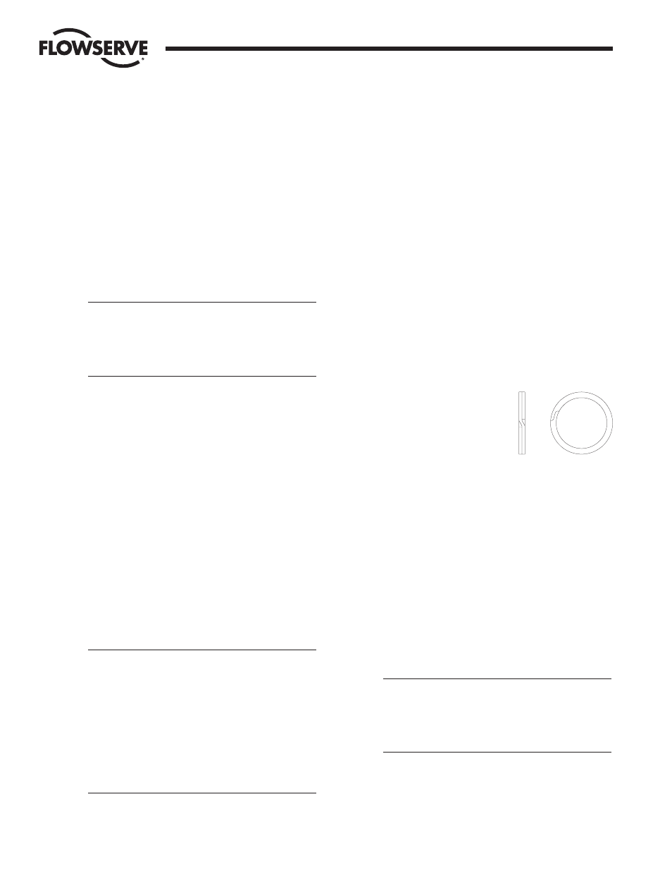
NOTE: Some actuators may be
using a spiral-ring type shaft
clip as shown at right.
To remove this clip, engage the
lower end of the ring with a flat
blade screwdriver. Using another
flat blade screwdriver push the top end of the clip in the
opposite direction. As the clip I.D. expands lift the clip
from the shaft. The installation of a new clip would be the
above steps in reverse and ensuring that the edges of the
clip are properly seated in the shaft groove.
The Rev. R1 model, all sizes and the Rev. R3 through R6
models, sizes 25 through 42 have an anti-ejection ring
(15J) that is a one-piece spiral wound ring. This ring does
not have to be removed and may or may not be included
in repair kits.
For Rev. R1 models, remove shaft clip (15F) (not a
reusable part!) (see note on bottom of page 10) and the
stainless steel washer from the shaft. Then remove the
top pinion bearing (15G) and the bottom pinion bearing
(15H) by carefully prying them away from the body.
CAUTION: Both of these bearings may have a projecting
“nib” which locates the bearings to the actuator body.
Be careful not to break off these nibs inside the body
when removing the top and bottom bearings.
Note: Top
bearing is marked “Top”. Bottom bearing has a larger
ID than the top bearing.
Next, slide the shaft out through the bottom of the body
and remove the top O-ring (15D) and the bottom O-ring
(15E) from the body.
Flow Control Division
Worcester Controls