18 valve maintenance, 19 basic sealant injection, Nordstrom valves – Flowserve Nordstrom Dynamic Balance Plug Valve and Double DB Plug Valve User Manual
Page 16
Flow Control
Nordstrom Valves
16
Dynamic Balance
®
Plug Valve and Double DB
®
Double Isolation Plug Valve
FCD NVENIM2005-01
5.18 Valve Maintenance
Proper valve performance depends on:
• Periodic injection of sealant to maintain adequate sealant pressure
in the valve to ensure positive shutoff and smooth operation.
• Selecting the correct Nordstrom Valve Sealant for the valve service
conditions. Because of variations in the product temperature, line
pressure, and frequency of valve operation, proper sealant selec-
tion is essential. An all-purpose valve sealant or lubricant does not
exist. Only the correct Nordstrom Valve Sealant can assure proper
valve performance.
• The proper application of the correct sealant. Knowing how to
correctly inject sealant will keep the Dynamic Balance Plug Valve in
proper working order without removing it from the line.
Be sure to remember:
Sealant injection may be performed with the valve in-line and under
pressure.
a
CAUTION: High pressures are generated during sealant
injection. It is recommended that safety glasses and thick
leather gloves be worn during sealant injection. Never
attempt to attach or detach the 400-D Hand Gun or Hypre-
gun-Plus while the gun hose is pressurized.
5.19 Basic Sealant Injection
1. Before injecting sealant into the valve, determine if the valve is
fully open or closed. Although the Dynamic Balance Plug Valve
can be lubricated with the Plug in any position, either the full
open or full close position allows the Sealdport groove system to
completely distribute the pressurized sealant to the valve seating
surfaces.
a
CAUTION: Extreme caution should be used when injecting
sealant into a valve in the closed position with an incom-
pressible fluid in the valve.
2. Find the Sealant Injection Fitting located on the side of the valve.
Remove any debris from the face of the sealant fitting and attach
the sealant injection device to the fitting. Be careful not to dam-
age the fitting in any way. A smooth contact surface is necessary
to ensure that an adequate seal is formed between the Button
Head coupler and the Sealant Fitting.
3. To inject sealant, follow the operating instructions for the injec-
tion equipment that you are using.
4. To help you determine if there are valve seat leakage problems,
four gauge scenarios are listed below. Once you have identified
the applicable gauge scenario, you can apply the appropriate
maintenance procedures, found in the specific valve mainte-
nance manual, to ensure that the valves are operating at their
peak condition.
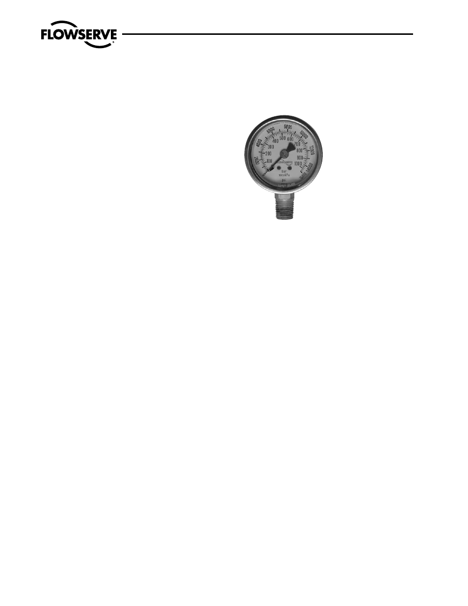
Figure 3 – Gauge
Gauge Scenario One The gauge does not indicate a pressure
increase above the initial pressure required to inject sealant into
the valve.
Assuming your injection equipment is operating correctly, there
are two possible reasons:
a. The sealant system is not full.
b. The seat is leaking. Leakage may be caused by too loose an
adjustment or damage to the valve’s seating areas.
Gauge Scenario Two As sealant is injected, the gauge
indicates a gradual increase in pressure until an initial plateau is
reached, then at some point the pressure increases to a higher
plateau and abruptly falls back to a lower level.
This scenario indicates that the valve is receiving sealant prop-
erly, the valve sealant system has filled, and the Plug has moved
off the seat. Even though this scenario shows that the Plug has
moved off the seat, it is still possible that the valve may be dif-
ficult to operate. Operation difficulties may be caused by:
a. Too tight an adjustment
b. Stem corrosion
c. Gearing problems (on gear-operated valves)
d. Actuator Problems (on actuated valves)
Gauge Scenario Three This scenario is much like Scenario
Two except that the sealant pressure gauge reaches a plateau
and remains at that point as the injection equipment is operated,