Flowserve Valtek StarPac 1 Intelligent Control Systems User Manual
Page 15
41-15
Flowserve Corporation, Valtek Control Products, Tel. USA 801 489 8611
Figure 15: Thermocouple Installation
Set
screw
Three-wire position
sensor cable
Eight-wire pressure
sensor cable
Board Stack Replacement (Model NT)
Inside the electronic housing cover and under the white
plastic shroud of a StarPac unit are five printed circuit
boards, together referred as the board stack. This design
allows each board to have a single purpose, which
simplifies troubleshooting and diagnostic procedures.
(Refer to Figure 7 on page 7.)
If, after consulting with the local Flowserve or factory
representative, the StarPac system's computer board
stack is found defective and needs replacement, pro-
ceed as follows. (Prior to proceeding, make sure a copy
of the configuration .CCT file is saved and available.)
1. Disconnect the power and air supply to the unit.
2. Remove the StarPac electronics assembly cover.
WARNING: Never remove the StarPac electron-
ics assembly cover if explosive atmospheres
are present; otherwise, injury to personnel can
occur.
3. Remove the plastic shroud by unscrewing the three
board assembly screws. Carefully grasp the top
four computer boards and pull them away from the
bottom board holding it in place. Disconnect the
three-wire hallpot and eight-wire process harness
connectors and set the four computer boards aside.
4. Unplug the temperature sensor wires from the
terminal block marked 'T/C' on the second com-
puter board.
5. Disconnect the three remaining wire harness con-
nections and carefully remove the bottom computer
board from the StarPac housing base. Some resis-
tance will be felt as the air pressure connections
disengage.
6. Unplug the new NT bottom board from the rest of
the stack. Plug the two interface connectors from
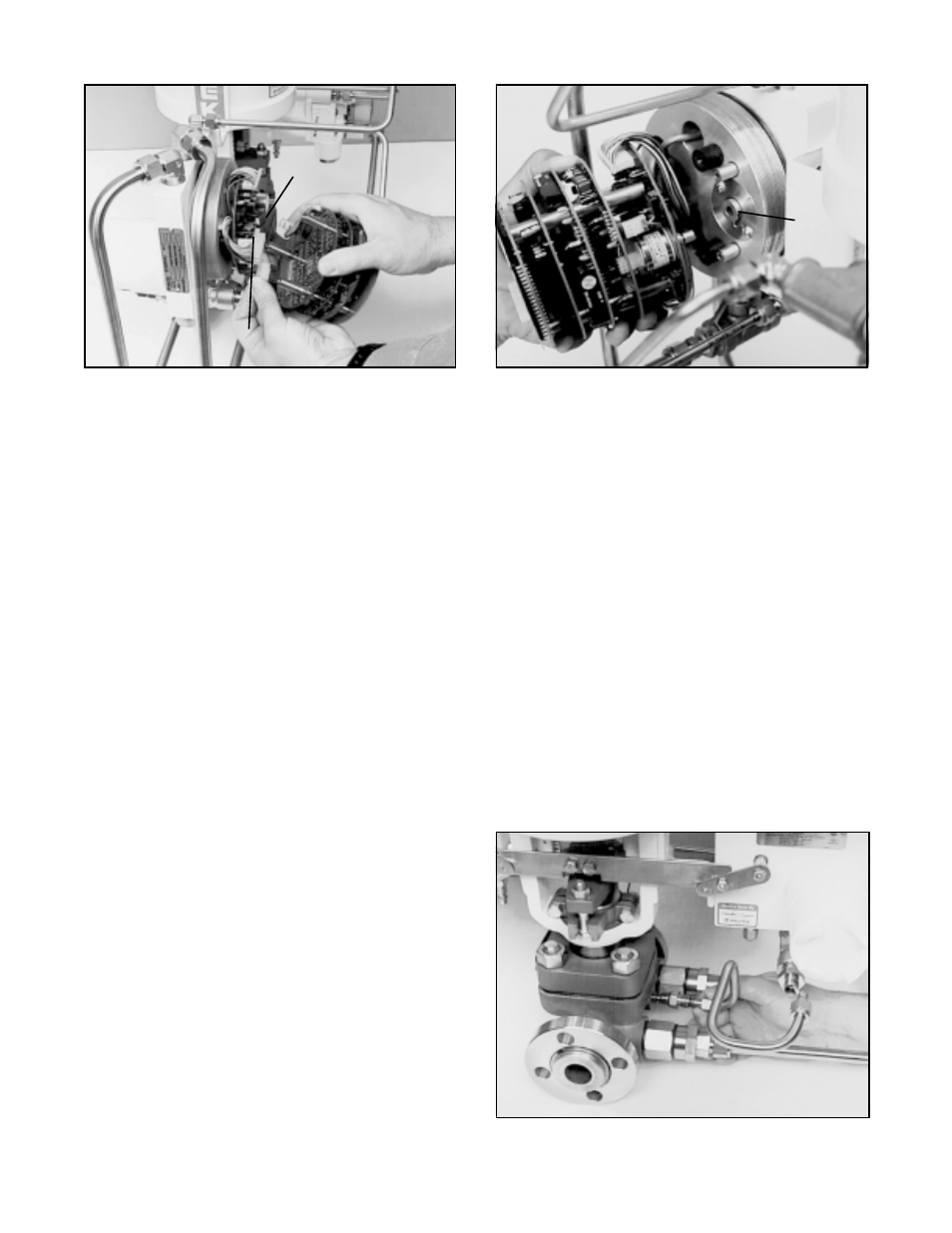
Figure 13: Removing Top Four Boards
Figure 14: Position Sensor Alignment
(Model SPxx)
the user interface into their appropriate connectors
on the bottom of this board. Twisting the connector
once prior to plugging it into the board will keep the
wires bundled together and out of the way. Also,
folding the wires flat against the base will keep them
from pushing the board away from the base.
7. Carefully align the two actuator pressure trans-
ducer nipples into their pressure standoffs and
press firmly on the top of the two transducers to seat
them into the standoffs and hold the board in place.
The board is properly seated when the pressure
standoffs are almost flush against the bottom of the
board.
CAUTION: To avoid damaging the nipples, do
not twist or bend the board once the nipples are
plugged in.
(Using one of the assembly screws
to hold the board in alignment while attaching
the other wires and boards will help prevent
this.)