Read holding register command (03) – Flowserve L75 Series Electric Actuator User Manual
Page 11
11
L75 Series Electric Actuator — Modbus RTU FCD LMAIM7502-00 – 07/05
flowserve.com
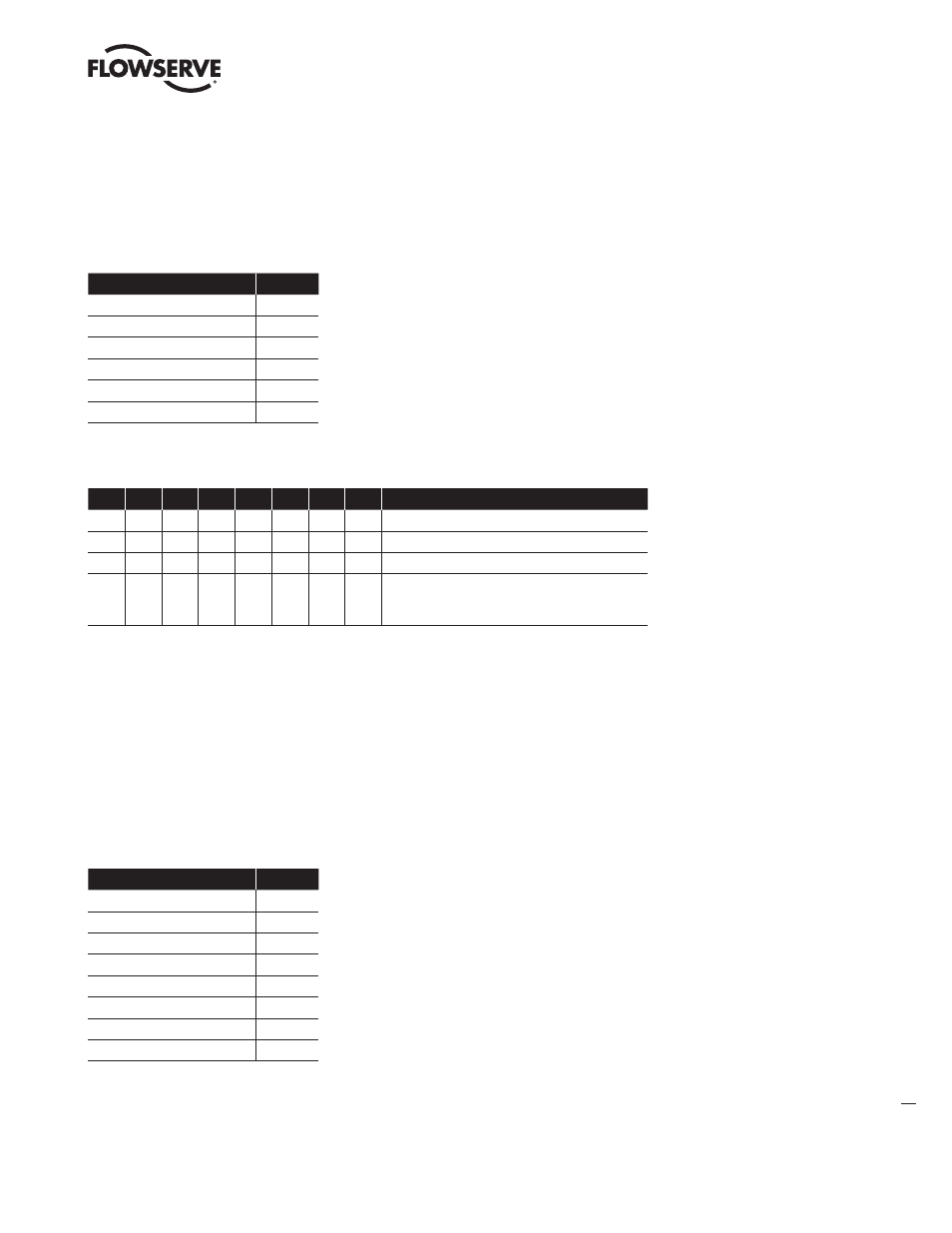
Response to a Read Input Status Command
Because two points were requested, bit 0 in the data field is the state of the CCW limit switch and bit 1
is the state of the CW limit switch (see the table below). For either bit, a 1 means the switch is activated
(closed) and a 0 means the switch is deactivated (open). In the example below, only the CW limit switch
is activated.
Field Name
Example
Actuator Address Returned
05
Function (Read Input Status)
02
Byte Count
01
Data
02
CRC Error Check (LS byte)
21
CRC Error Check (MS byte)
79
The bytes returned (in hex) to the master in the above example would be: 05, 02, 01, 02, 21, 79
Data Byte When Two Limit Switch Statuses are Read
7
6
5
4
3
2
1
0
status
0
0
Both CW and CCW limit switches are OFF
0
1
CCW limit switch is ON, CW limit switch is OFF
1
0
CW limit switch is ON, CCW limit switch is OFF
1
1
If the actuator has been properly calibrated, this
state will never be returned since both switches
should not be on at the same time.
Read Holding Register Command (03)
This command reads the state of both end-of-travel limit switches, as well as actuator motion. The CW
limit switch detects end-of-travel in the clockwise direction and is at register location 40,009 (bit 0) and
40,012 (bit 5); the CCW limit switch detects end-of-travel in the counterclockwise direction and is at
register location 40,009 (bit 1) or 40,012 (bit 3); the stopped motion holding register is 40,009 (bit 2);
the CW motion holding register is 40,009 (bit 3); the CCW motion holding register is 40,009 (bit 4). All
register bit locations must be requested simultaneously by reading each register entirely. Broadcast is
not supported.
Example: “Read holding register 40, 012 for CW and CCW limit switch statuses of actuator #1”
Field Name
Example
Actuator Address
01
Function (Read Coil Status)
03
Starting Address (High)
00
Starting Address (Low)
0B
Number of Points (High)
00
Number of Points (Low)
01
CRC Error Check (LS byte)
F5
CRC Error Check (MS byte)
C8
The bytes sent (in hex) to the actuator in the above example would be: 01, 03, 00, 0B, 00, 01, F5, C8