Response to a read holding register command, Force single coil command (05), Response to a force single coil command – Flowserve L75 Series Electric Actuator User Manual
Page 12
L75 Series Electric Actuator — Modbus RTU FCD LMAIM7502-00 – 07/05
12
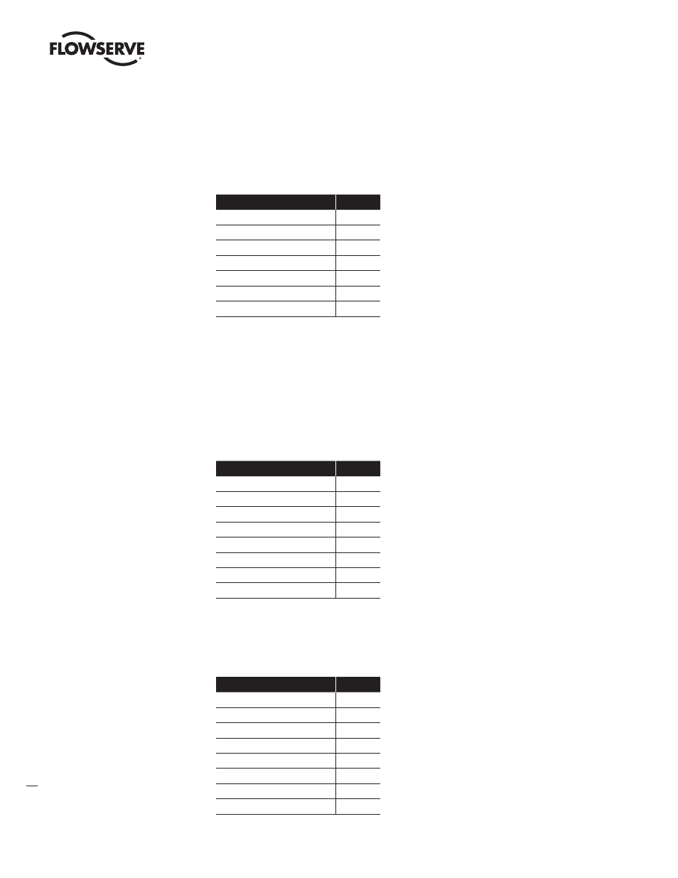
Response to a Read Holding Register Command
Because 1 register was requested, bit 3 in the data field is the state of the CCW limit switch and bit 5 is
the state of the CW limit switch. For either bit, a 1 means the switch is activated (closed) and a 0 means
the switch is de-activated (open). In the example below, the low data byte is read as 00001000 since
only the CCW limit switch is activated.
Field Name
Example
Actuator Address Returned
01
Function (Read Input Status)
03
Byte Count
02
Data Hi
00
Data Lo
08
CRC Error Check (LS byte)
B9
CRC Error Check (MS byte)
82
The bytes returned (in hex) to the master in the above example would be: 01, 03, 02, 00, 08, B9, 82
Force Single Coil Command (05)
This command sets the state of a specific motion control circuit. Coil 1 is the CW motion control
circuit; coil 2 is the CCW motion control circuit. A force data of FF00 will either start or continue valve
movement; a force data of 0000 will stop valve movement. Other data values will return an exception
response. Only coil 1 and coil 2 are supported. Broadcast is not supported.
Example: “Direct actuator #5 to travel in the CW direction”
Field Name
Example
Actuator Address
05
Function (Force Single Coil)
05
Coil Address (High)
00
Coil Address (Low)
00
Force Data (High)
FF
Force Data (Low)
00
CRC Error Check (LS byte)
8D
CRC Error Check (MS byte)
BE
The bytes sent (in hex) to the actuator in the above example would be: 05, 05, 00, 00, FF, 00, 8D, BE
Response to a Force Single Coil Command
The normal response is an echo of the original command, returned after the coil has been forced.
Field Name
Example
Actuator Address
05
Function (Force Single Coil)
05
Coil Address (High)
00
Coil Address (Low)
00
Force Data (High)
FF
Force Data (Low)
00
CRC Error Check (LS byte)
8D
CRC Error Check (MS byte)
BE
The bytes sent (in hex) back to the master in the above example would be: 05, 05, 00, 00, FF, 00, 8D, BE