Worcester actuation systems, Sample rs-485 connection – Flowserve DFC17 User Manual
Page 11
Advertising
WCAIM2026
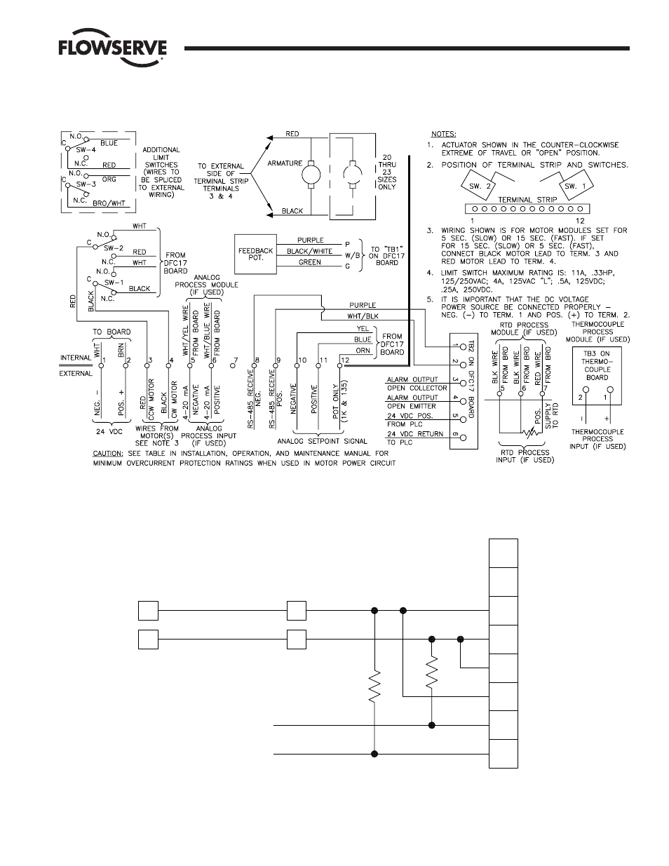
DataFlo Digital Electronic Controller DFC17 Installation, Operation and Maintenance Instructions
11
Flow Control Division
Worcester Actuation Systems
Figure 4 – 24 VDC DFC17 Circuit Board Wiring
Figure 5
ICS
Model 485F9 (9 pin)
or 485F (25 pin)
485 Converter
1.5K
1.5K
PWR SUPPLY +9 VDC
PWR SUPPLY GND
TB2
TB2
2
1
9
8
Receive -
Receive +
Wht/Blk
Purple
Internal
External
Actuator Terminal
Strip
(SHIELD)
(NO CONNECTION)
EN\
GND
TX
TX\
RX\
RX
GND
VDC
Sample RS-485 Connection
Controller Board
NOTE: If you are not using the RS-485 converter as shown in Figure 5, then refer to the documentation that came with your converter for proper
connections.
Advertising
See also other documents in the category Flowserve Hardware:
- Tandem Seal (8 pages)
- 978 Chemiepac (12 pages)
- ISC2 Single Pusher Repair (8 pages)
- LS-300 Series Durametallic (4 pages)
- Pac-Seal Type 16 (8 pages)
- U Series BW Seals (4 pages)
- ISC2 Dual Pusher Repair (12 pages)
- ISC2 Single metal bellows seal (8 pages)
- Durametallic Double CRO (8 pages)
- VRA-C Series Durametallic (4 pages)
- ISC2 Dual metal bellows sea (12 pages)
- Single Inside Pusher Type Seal (8 pages)
- Bearing Gard (2 pages)
- X-200 (12 pages)
- GTS Series (12 pages)
- MSS Series (12 pages)
- SLC Series Interseal (12 pages)
- QB Series BW Seals (8 pages)
- SLM-6100 (12 pages)
- SLM-6200 (12 pages)
- High Temperature Metal Bellows Seals (8 pages)
- X Series BW Seals (8 pages)
- ML-200 Series Durametallic (8 pages)
- ML-200 Series Durametallic (8 pages)
- Circulator (12 pages)
- ISC Series (16 pages)
- Gas Barrier Control System (4 pages)
- CPM Series (8 pages)
- CPM Series (12 pages)
- Mechanical Seal and Seal Support System Storage (4 pages)
- RIS Seal (12 pages)
- 682 Seal Cooler (8 pages)
- ISC2 Series (8 pages)
- ISC2 Series (116 pages)
- Pac-Seal Type 52 (8 pages)
- Pac-Seal Type 31 (8 pages)
- ST Series (8 pages)
- Mechanical Seal General (16 pages)
- Dual Pressurized Seals (8 pages)
- Uniseal Series BW Seals (8 pages)
- XLC Series (8 pages)
- PSS II Durametallic (8 pages)
- PSS II (16 pages)
- ISC1SX (8 pages)
- ISC1PX (8 pages)