Worcester actuation systems – Flowserve DFC17 User Manual
Page 25
WCAIM2026
DataFlo Digital Electronic Controller DFC17 Installation, Operation and Maintenance Instructions
25
Flow Control Division
Worcester Actuation Systems
6.2 Symptom Table
SYMPTOM
GUIDELINES TO FOLLOW
6.2.1
Actuator will not operate in either direction (no sound from motor(s)).
6.3.1, 6.3.2, 6.3.3, 6.3.4, 6.3.5,
6.3.6, 6.3.7, 6.3.10
6.2.2
Actuator will not operate in either direction
6.3.2, 6.3.3, 6.3.4, 6.3.5, 6.3.6,
(humming or buzzing sound from motor(s)).
6.3.9, 6.3.10, 6.3.11, 6.3.12
6.2.3
Actuator slowly moves in one direction on its own.
6.3.4
6.2.4
Actuator runs normally for 7-8° while coming off limit switch,
6.3.4, 6.3.15
then slows down or stops (motor(s) hum or buzz).
6.2.5
Actuator oscillates intermittently or upon reaching a new position.
6.3.2, 6.3.8, 6.3.13
6.2.6
Actuator runs slowly in one or both directions,
6.3.2, 6.3.4, 6.3.9, 6.3.10,
but otherwise operates normally.
6.3.11, 6.3.12
6.2.7
Actuator works intermittently.
6.3.2, 6.3.10, 6.3.12
6.2.8
Actuator runs normally in one direction but will
6.3.2, 6.3.4, 6.3.7
not operate in the other direction (no hum or buzz from motor(s)).
6.2.9
Actuator will not move valve after a stop when signaled to travel in
6.3.14
same direction as previous command.
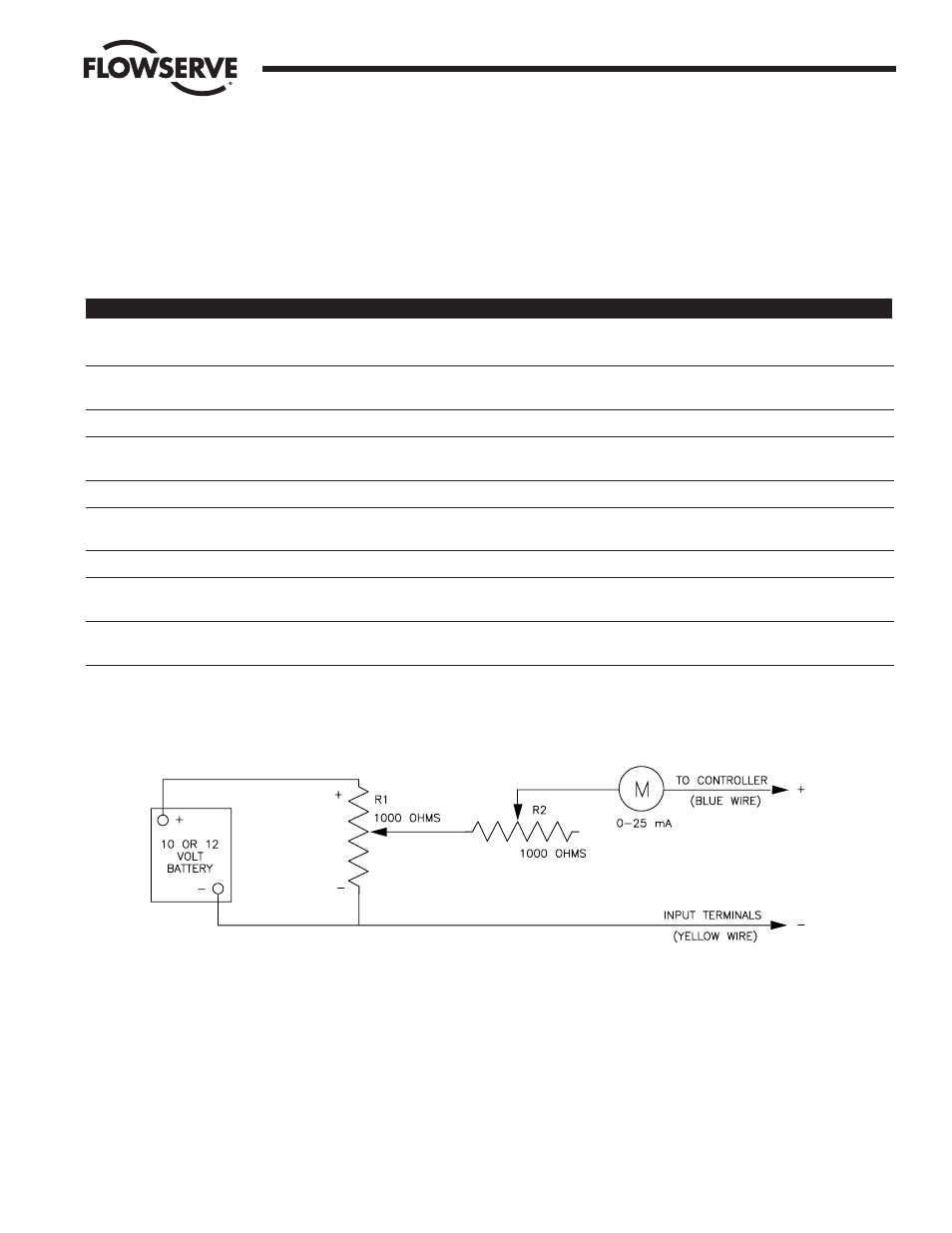
Test Unit for Milliamp Setpoint Input Controller – Set R1 all the way toward the plus end. Adjust R2 for a 20 mA reading. Varying R1 will now
provide input signals between 4 and 20 milliamps.
Figure 6 Simple 4–20 mA Supply Circuit
C. Install new circuit board onto the brackets using the
procedure in paragraph B above in reverse order.
Tighten the mounting screws so that the grommets
are about half compressed. Note that 23 size 75
actuators use a spacer in place of a grommet at the
transformer support bracket.
D. Make electrical connections per the appropriate wiring
diagrams (see section 3.0). Feed the 3 feedback pot
wires up through the hole in the board near TB1 (see
figure 1 on either page 6 or 7).
E. Calibrate the new circuit board per Part 4.2