Operation – Flowserve CEA Series Limitorque Automax User Manual
Page 6
Limitorque Worcester Controls CEA Series FCD WCENIM2080-00-AQ 12/14
6
Normally there are no orientation restrictions for actuator mounting;
consult factory with any questions. Typical installations include In-
Line mounting with the handwheel in line with the piping and Cross-
Line mounting with the handwheel cross line with the piping.
NOTE: Mechanical assistance may be required to remove and
tighten the threaded covers. A flat edge screwdriver 10 inches or
longer may be of assistance.
NOTE: It is not necessary to remove the indicator dome on the
Controls Cover for removal.
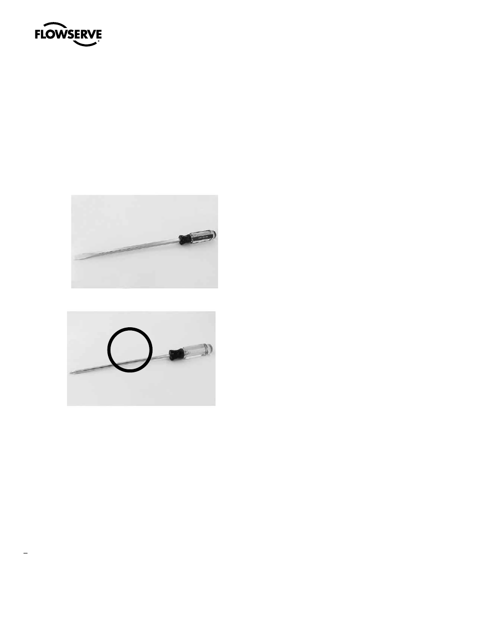
Flat Edge Screwdriver (recommended)
Round Edge Screwdriver (not recommended)
After commissioning the actuator, the threaded cover(s) will need to be
installed in reverse fashion. Rotate by hand until difficult to turn (about
90% complete). Use mechanical assistance until you feel the cover
“bottom out.” For the controls cover to be properly sealed, the gap
between the cover and the housing should be no more than 0.010 inch.
With the actuator in full CW position, the entire RED closed indicator
should be shown in the viewing window of the dome. This is the
factory default setting. User may change to CCW/Open position.
a
WARNING: All threaded covers must be installed with the above
criteria, otherwise NEMA/IP and Hazardous Area ratings could
be compromised.
Operation
C-PRO version
The C-PRO, ON/OFF voltage control actuator ships from the factory
calibrated and ready to operate. It is not necessary to remove the Controls
Cover if factory settings are suitable. Wire the actuator according to the
wiring diagram located inside the Terminal Block cover.
Key default settings include:
• Factory calibrated for 0-90 degree operation
• CCW to Open, CW to Close
• Fastest operating speed (listed on nameplate)
• Maximum rated torque (listed on nameplate)
• L1 and L2 are for input voltage 120 or 240VAC (Consult Factory for
other AC/DC voltages)
• Terminals 20, 21, 22 and 23
- Terminal 20 = voltage command common
- Terminal 21 = voltage command OPEN
- Terminal 22 = voltage command CLOSED
- Terminal 23 = voltage command MID
• Terminals 1 and 2 are Normally Open (NO) dry relay contacts for
OUTPUT 1 (CCW)
• Terminals 3 and 4 are Normally Open (NO) dry relay contacts for
OUTPUT 2 (CW)
• Terminals 5 and 6 are Normally Open (NO) dry relay contacts for
OUTPUT 3 (Torque or MID)
• Terminals 7 and 8 are Normally Open (NO) dry relay contacts for
OUTPUT 4 (Compartment Temp)
NOTE: L1 and L2 are to be powered at all times. Remote voltage
commands can be any voltage between 24VDC-240VDC or
24VAC to 240VAC: 4/5 wire power and control scheme.
For 3 wire power and control scheme, consult Flowserve.
X