1 c-mod wiring – Flowserve CEA Series Limitorque Automax User Manual
Page 7
7
Limitorque Worcester Controls CEA Series FCD WCENIM2080-00-AQ 12/14
flowserve.com
C-MOD version
The C-MOD or Modulating control actuator ships from the factory
calibrated and ready to operate. It is not necessary to remove the Con-
trols Cover if factory settings are suitable. Wire the actuator according
to the wiring diagram located inside the Terminal Block cover.
Key default settings include:
• Factory calibrated for 0-90 degree operation
• Direct Acting CCW to Open
• L1 and L2 are for input voltage 120 or 240VAC (Consult Factory for
other AC/DC voltages)
• Terminals 11, 12, 13 and 14
- Terminal 11 = + 4-20mA current source (input)
- Terminal 12 = ( - ) 4-20mA current source (input)
- Terminal 13 = + Loop Powered 24VDC + 4-20mA current
(output)
- Terminal 14 = ( - ) Loop Powered 24VDC + 4-20mA current
(output)
• Terminals 1 and 2 are Normally Open (NO) dry relay contacts for
OUTPUT 1 (CCW)
• Terminals 3 and 4 are Normally Open (NO) dry relay contacts for
OUTPUT 2 (CW)
• Terminals 5 and 6 are Normally Open (NO) dry relay contacts for
OUTPUT 3 (Torque or MID)
• Terminals 7 and 8 are Normally Open (NO) dry relay contacts for
OUTPUT 4 (Compartment Temp)
NOTE: L1 and L2 are to be powered at all times
NOTE: 4-20mA output is to be loop powered with 24VDC.
Voltage range 13-24VDC.
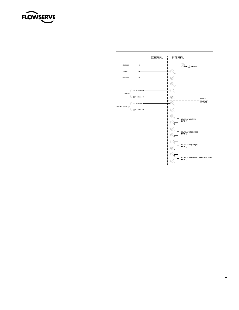
2.1 C-MOD Wiring
NOTE 1: Contact rating = 16amp @ 250VAC, dry contact. All outputs
are programmable, remote voltage inputs are 12VDC
to 240VAC for Open, Closed, Mid/Dribble terminals
(20,21,22,23)