Flowserve 90 Series Limit Switch Kit User Manual
Introduction
Worcester Controls
WCAIM2044
(Part 18472)
Limit Switch Kit for Series 90
Modular Accessory System
Installation, Operation and Maintenance Instructions
INTRODUCTION
NOTE: For M.A.S. housing assembly, installation, and maintenance
instructions, refer to Installation, Operation, and Maintenance Manual
WCAIM2005.
A variety of mechanical and proximity switch options are available for
the Series 90 Modular Accessory System. The switches can be used
to provide actuator position indication or to control other equipment.
Only one option is available in an M.A.S. unit at a time.
Options always available (regardless of other options) are:
M2 – Two Single-Pole, Double-Throw Mechanical Switches
P6 – Two Two-Wire AC Proximity Switches
P8 – Two Three-Wire DC Proximity Switches
Options with limited availability (not available with output
potentiometer options or with positioner/controller):
M4 – Four Single-Pole, Double-Throw Mechanical Switches
D2 – Two Double-Pole, Double-Throw Mechanical Switches
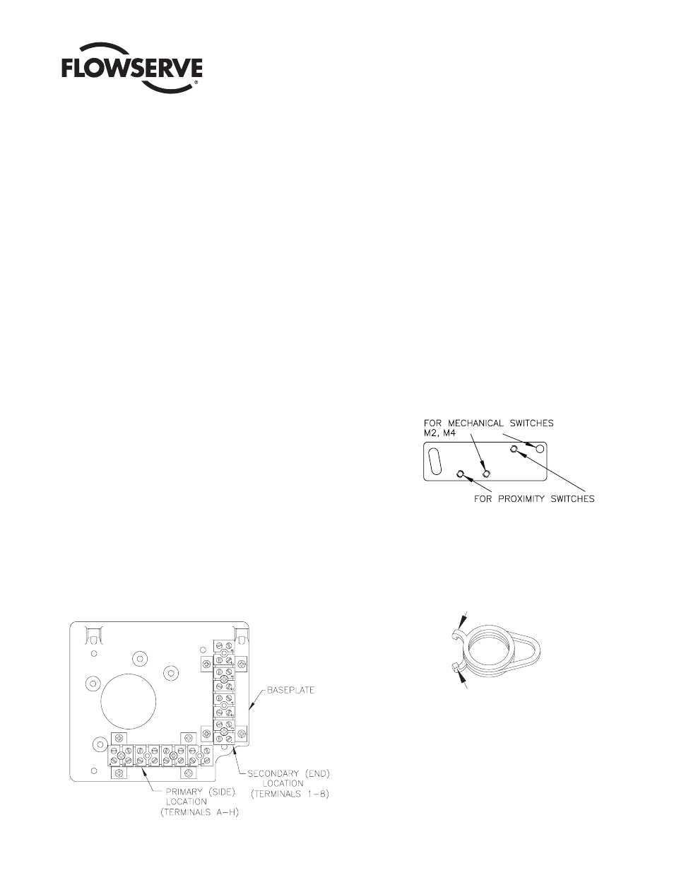
The switch options require differing numbers of terminal connections.
Where required, (M4, D2), the additional terminal strip will be
provided in the M.A.S. unit or switch kit. It will be located in the
“secondary” location as shown.
An “Adjustment Plate” is used to mount the proximity and some
single-pole mechanical switches to the baseplate. This allows the
proximity switches to be adjusted to their optimum sensing distance
for the most accurate operation. If mechanical switches are to be
mounted to this adjustment plate, then the plate should be set to a
middle position—not rotated toward or away from the shaft. There
are two sets of mounting holes in the adjustment plate which are
used to accommodate the various switches. See figure below. Their
use will be detailed later.
The cams used to actuate the switches offer unlimited positioning
without the use of tools. These cams are essentially “wrap-springs”
and grip the shaft tightly enough to prevent accidental rotation.
Squeezing together the two small protrusions from the cam loosens
the spring and allows adjustment. Needle nose pliers may prove to be
helpful when installing the cams, but are not required.
NOTE: If potentiometer option is also going to be installed, the
potentiometer face gear should be installed before the switches and
cams.
SQUEEZE
SQUEEZE