Operation – Flowserve 90 Series Limit Switch Kit User Manual
Page 4
4. OPERATION
a. Once the M.A.S. unit has been assembled and connected to the
actuator, the switch cams can be set per user’s requirements.
Normally switch I (and III) indicates “closed” and switch II (and
IV) indicates “open.”
b. FOR P6 and P8: Loosen the #4-40 screws used to mount the
switch adjustment plate. Set the switches such that the cams will
approach the switch face as closely as possible without making
contact. Retighten the screws.
c. The unit should be operated to ensure that switch actuation
occurs at the end of rotation (or in whatever position is desired by
the customer) repeatably.
Flow Control Division
Worcester Controls
4
Limit Switch Kit for Series 90 Modular Accessory System
WCAIM2044
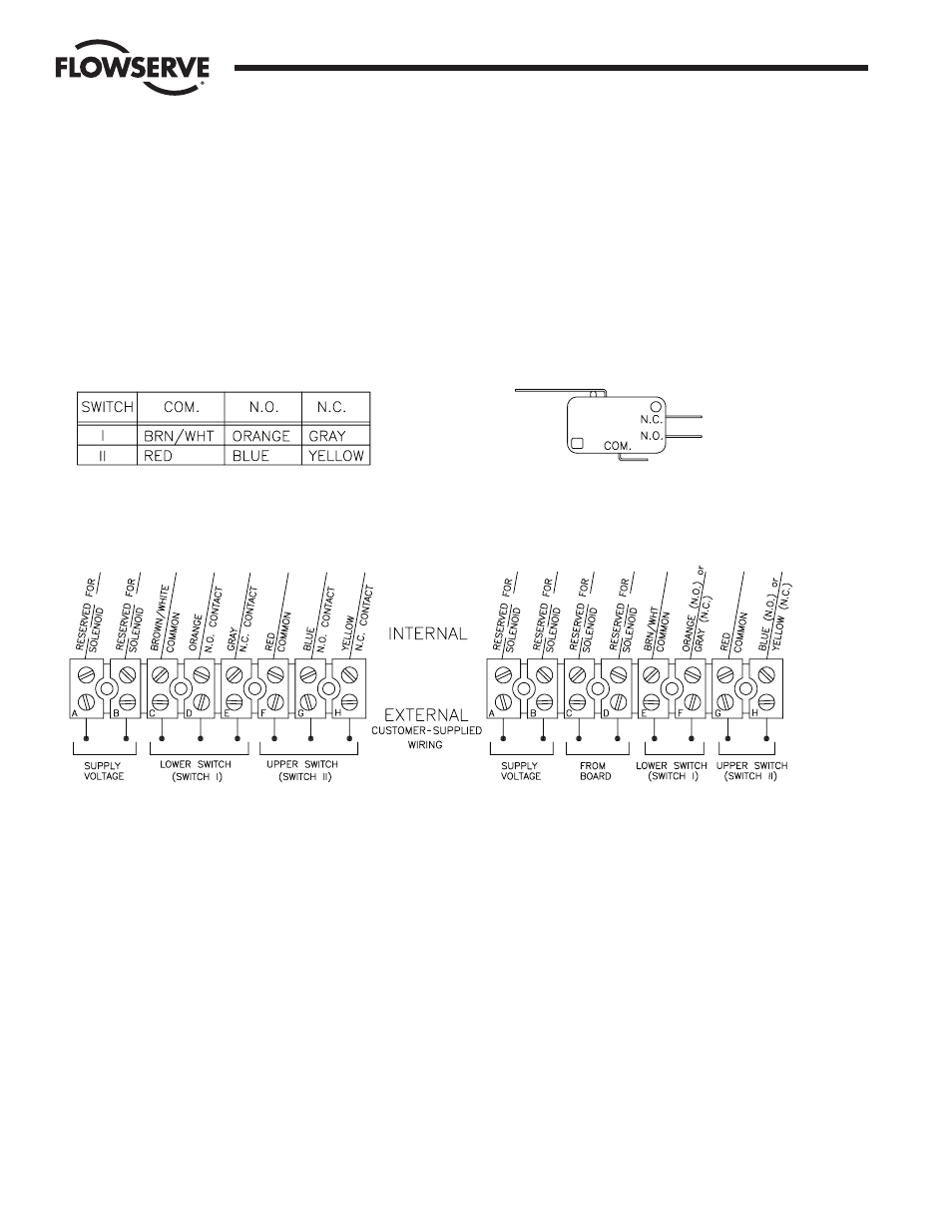
M2
M2 Without Positioner/Controller Option
M2 With Positioner/Controller Option
See
paragraph
3.d