Cams, Wiring, Worcester controls – Flowserve 90 Series Limit Switch Kit User Manual
Page 3
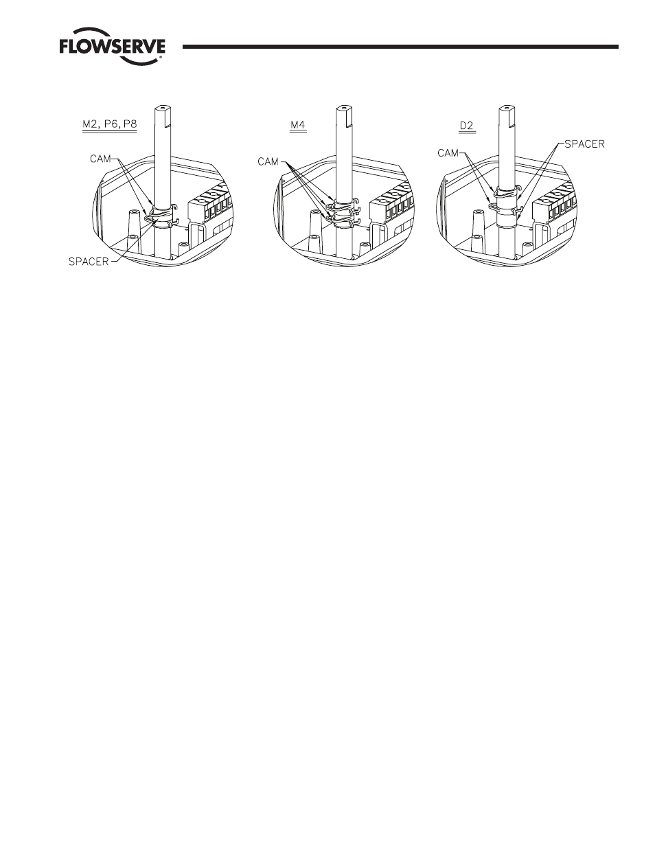
2. CAMS
To work the spring cams down the shaft, squeeze the two protrusions
and turn. Follow the sketch for the appropriate option:
M2, P6, P8: Assemble the first spring cam, the spacer, and second
spring cam.
M4: Assemble the four spring cams with no spacers.
D2: Assemble one spacer, one spring cam, second spacer, and
second cam.
3. WIRING
NOTE: All wiring is to be run smoothly and neatly and away from any
rotating parts, using wire ties if necessary. Use caution to avoid
pinching wires and/or solenoid rectifiers (if used) between the base
and cover flanges.
All wiring to terminal strips shall be inserted only to mid-point of
terminal strips.
a. For M4 and D2 options, add the second terminal strip in the
“secondary” location using the four #4 x
3
/
8
" self-tapping screws
provided.
b. The wire leads will be connected to the switches as provided. Pay
close attention to the switch labels, schematics, wire colors, etc.
when wiring the switches.
c. Route the wires between the legs of the black terminal brackets
whenever possible. Be certain that the wires will not get fouled on
the shaft when it rotates.
d.
NOTE: For M2 switch option when used with Positioner or
Controller (PC90) option:
Due to wiring requirements of the positioner or controller (PC 90)
options, only four switch leads can be accommodated. The user
must decide whether the switches are to be wired as normally
open (N.O.) or normally closed (N.C.). Normal two-wire switch
operation is to use the N.O. contact. If switch operation requires
the N.C. contact to be used, the wiring diagram inside the cover
should be marked to reflect this modification. In either case, the
unused wire should be removed. If both sets of contacts must be
used, the third wire from each switch (N.C.) can be directly
connected.
e.
NOTE: For P8 switch option when used with positioner or
controller (PC 90) option:
Due to wiring requirements of the positioner or controller (PC 90)
options, only four switch leads can be accommodated. In the case
of the P8 DC proximity switches, three wires for each switch are
required for operation. The “load” wires (brown/white on switch I
and red on switch II) must be connected directly to the
customer’s incoming wiring, without going through the terminal
strip.
Flow Control Division
Worcester Controls
WCAIM2044
Limit Switch Kit for Series 90 Modular Accessory System
3