Squeeze, Worcester controls – Flowserve I90 Series Intrinsically Safe Modular Accessory System User Manual
Page 10
not rotated towards or away from the shaft. There are two sets of
mounting holes in the adjustment plate; use the appropriate set as
shown in Figure 16. Their use will be detailed later.
The cams used to actuate the switches offer unlimited positioning
without the use of tools. These cams are essentially “wrap-
springs” and grip the shaft tightly enough to prevent accidental
rotation. Squeezing together the two small protrusions from the
cam, as shown in Figure 17, loosens the spring and allows
adjustment. Needlenose pliers may prove to be helpful when
installing the cams, but are not required.
NOTE: If potentiometer option is also going to be installed, the
potentiometer face gear should be installed before the switches
and cams.
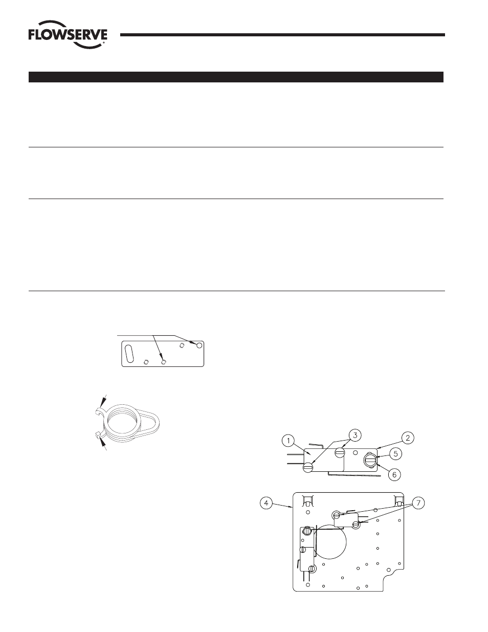
1. ASSEMBLY
a. M2 – TWO SPDT MECHANICAL SWITCHES
1. Stack two (2) switches (item 1) and attach to the
adjustment plate (item 2), as shown in Figure 18
below, using two (2) #4-40 x 1" screws (item 3)
provided.
Note: One of the screws will thread into a tapped hole
in the adjustment plate while the other engages a
clearance hole without threads.
FOR MECHANICAL SWITCHES
M2
Figure 16
SQUEEZE
SQUEEZE
Figure 17
Flow Control Division
Worcester Controls
10
Intrinsically Safe Modular Accessory System (Series I90)
WCAIM2033
PROBLEM
POSSIBLE CAUSE(S)
SOLUTION
Air leak between
Loose solenoid
Tighten solenoid.
solenoid/block or
between block/housing
Gasket out of position
Remove solenoid block, realign gasket and
reattach solenoid block.
Defective gasket
Contact Flowserve for replacement.
Rough surfaces on solenoid block
Contact Flowserve for replacement.
Solenoid does not
Power supply not connected/not working
Check power supply.
energize (go on)
Defective lead wires
Check leads with ohmmeter or try new lead
wires.
Defective solenoid valve
Contact Flowserve.
Solenoid okay — actuator
High valve torque
Disconnect valve and check operation/torque.
not working correctly
Air supply not connected/low pressure
Check supply air piping and pressure.
Tubing connections to M.A.S.; or solenoid block tubing not correct
Check M.A.S. air connections.
Debris in solenoid valve or block
Remove and clean solenoid valve and block.
Check filtering per Section III.B.
No obvious cause(s)
Disconnect M.A.S. from actuator; test each
unit separately.
Figure 18