Worcester controls – Flowserve I90 Series Intrinsically Safe Modular Accessory System User Manual
Page 6
j.
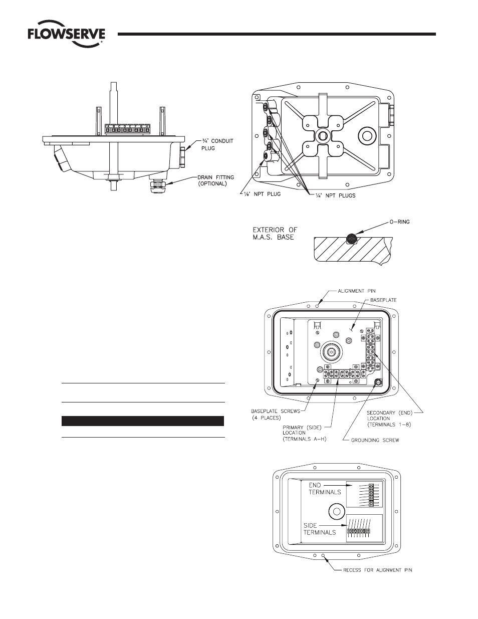
The M.A.S. uses a standard O-ring to achieve both
Watertight (TYPE 4) and Explosion-proof (TYPE 7)
ratings. Refer to Figure 8.
k. Refer to figure 9. The baseplate contains one factory-
assembled terminal strip located in the “primary” (side)
location on the baseplate. A second terminal strip is
required with some M.A.S. options, outlined below. The
extra terminal strip will be provided with the appropriate
options. Attach it to the baseplate with four (4) #4 x
C\,"
self-tapping screws provided in the “secondary” (end)
location.
l.
Assemble the baseplate into the base using the four (4)
#6-32 screws provided. Use care when tightening these
screws as the baseplate is plastic and could be damaged
if overtightened. If options such as Switches, Potentiometer
kit, etc., are to be installed, they can be assembled to the
baseplate prior to installing baseplate into base.
CAUTION: Avoid contacting baseplate with solvents —
damage may result.
OPTION REQUIRING SECOND TERMINAL STRIP*
FEEDBACK POTENTIOMETER - P
* INCLUDED WITH OPTION OR KIT IF REQUIRED.
m. The base is provided with an alignment pin pressed into
the flange, which will allow the cover to be assembled in
only one orientation (See Figures 9 & 10). Be certain the
cover is correctly positioned prior to tightening bolts, or
damage may result.
n. M.A.S. options are supplied with wiring diagrams which
should be affixed to the inside of the cover as shown in
Figure 10.
Note the orientation of the terminal strips on the wiring
diagrams, and their location in the cover.
Figure 10
Flow Control Division
Worcester Controls
6
Intrinsically Safe Modular Accessory System (Series I90)
WCAIM2033
Figure 7
Figure 9