Iii. operation and maintenance instructions, Worcester controls – Flowserve I90 Series Intrinsically Safe Modular Accessory System User Manual
Page 4
4. Cut the tubing provided to as short a length as possible that
will still reach comfortably from the Series I90 unit to the
actuator. On double-acting versions, the tubes run parallel to
each other and do not cross. The operation of the actuator
can be reversed by reversing the location of the tubes at the
actuator. Connect the tubes to their respective actuator and
Series I90 ports (refer to figures 2, 3, and 4).
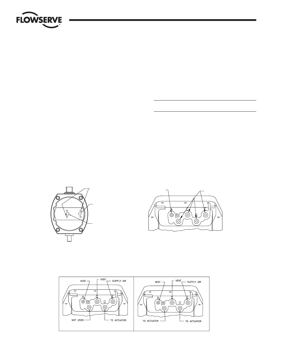
5. Refer to Figure 4 for a diagram of the Series I90 air
connections in each of its two configurations.
a. Connect the supply air for the actuator (80 psi
nominal/100 psi maximum) to the location labeled
“SUPPLY” in the appropriate sketch.
b. Locations labeled “VENT” may be fitted with a porous
muffler (or other fitting if desired) to reduce exhaust
noise. Air must be allowed to flow freely from these ports;
“VENT” locations must not be plugged under any
circumstances.
c. Ports labeled “NOT USED” must remain plugged with the
stainless steel pipe plugs provided.
III. OPERATION AND
MAINTENANCE INSTRUCTIONS
A. HOUSING ASSEMBLY
The housing consists of the base, cover, shaft, baseplate, and
associated hardware. The housing is assembled as received from
Flowserve. For ease of maintenance, assembly instructions will be
provided here.
1. COVER
CAUTION: Use care to avoid damaging the machined flange
surface of the cover.
a. Apply a light coat of Cindol 2321 lubricant (or other
bearing grease) to the shaft hole.
b. Assemble the captive type cover screws through the
flange holes. The screws must be turned through
approximately
Z\v" of thread until they reach the clearance
diameter and remain loose in the cover. Use caution to
avoid cross-threading these screws. Refer to Figure 5.
Flow Control Division
Worcester Controls
4
Intrinsically Safe Modular Accessory System (Series I90)
WCAIM2033
FIGURE 2 – ACTUATOR FITTING LOCATIONS
FIGURE 3 – M.A.S. FITTING LOCATIONS
FIGURE 4 – AIR CONNECTIONS FOR ALL I90 M.A.S. CONFIGURATIONS
#10–32 THREAD
4 PLACES REF.
(NOT USED)
PORT "S"
(CLOSEST TO EDGE
OF ACTUATOR)
PORT "D"
(CLOSEST TO CENTER
OF ACTUATOR)
¹⁄₈" NPT
¹⁄₄" NPT
SPRING-RETURN – USE ONE (1) STRAIGHT FITTING
IN PORT "D"
DOUBLE-ACTING – USE TWO (2) STRAIGHT FITTINGS:
ONE (1) IN PORT "D" AND
ONE (1) IN PORT "B"
DOUBLE-ACTING – USE TWO (2) ELBOW FITTINGS:
ONE (1) IN PORT "S" AND
ONE (1) IN PORT "D"
SPRING-RETURN – USE ONE (1) ELBOW FITTING
IN PORT "S"
DOUBLE-ACTING
SPRING-RETURN